
Last month in this space we tackled “Proper Rudder Use,” pointing out that in many situations involving angles of attack (AoA) at or near the stall, rudder and not aileron should be the control used to maintain both heading and a wings-level attitude. We also explored how rudder is used to compensate for adverse yaw, and presented a simple exercise pilots can use to demonstrate both its proper and improper application.
Of course, any complete discussion of how to use an airplane’s rudder must also include ailerons and the how and why of their workings, how they create adverse yaw and how we use rudder to maintain coordinated flight. Finally, we want to address an age-old question: Which to apply first when rolling into a banked turn: Rudder? Aileron? Both? Why?
How Ailerons Work
Ailerons change a wing’s AoA; lowering an aileron increases the wing’s AoA. Up to a point, increasing a wing’s AoA also generates greater lift. The wing with the greater lift wants to rise, which banks the airplane. On the other wing, usually, its aileron is deflected upward, decreasing its AoA and generating less lift. One of the results is a bank in the direction of the lowered wing, the one with the raised aileron.
One of the keys to understanding why we need rudder results from all the changes in generated lift when we deflect ailerons: Just as each wing’s relative lift increases or decreases, so does the drag being produced, exponentially. So, by generating greater lift on the lifting wing, we’re also experiencing greater drag.
The increased drag of the rising wing retards the aircraft’s rate of turn, but not its roll. In other words, as we bank right, the aircraft wants to yaw in the direction of the greatest drag. That’s opposite the direction in which we want to turn, so some rudder in the same direction as the bank is necessary. This yawing is the aforementioned “adverse yaw,” and conventional fixed-wing aircraft counter it with rudder application.
One way to address adverse yaw, the Frise aileron (pronounced “freeze” and named after L. G. Frise in 1928), has become commonplace on many personal airplanes. With this design, when the aileron is deflected upward, its leading edge protrudes, like a lip, downward into the airstream. This is illustrated in Figure 1 (Two Aileron Types Sidebar.) This “lip” creates drag, retarding the lowered wing and partly balancing simultaneously being created by the lowered aileron on the opposite wing. Thus, the two wings’ combined drag is somewhat equalized, which reduces the adverse yaw effect.
Another method engineers use to minimize adverse yaw is the differential aileron design, pictured in Figure 2 (Two Aileron Types Sidebar.) In this design, the ailerons don’t deflect to the same extent in each direction. Instead, their downward deflection—which, remember, increases the wing’s AoA and generated lift, raising the wing—is limited relative to the opposite aileron, which is designed to deflect much further, but in the upward direction. By restricting the ailerons’ downward deflection, drag on the raised wing is minimized, as is adverse yaw. Both of these common methods are described above in greater detail.
Turn Basics
Of course, we use ailerons to help control bank, roll rate and coordinated turns. As we’ve touched on, ailerons create drag when they’re deflected, and also can affect generated lift. Only when they’re in the neutral position is their aerodynamic impact eliminated. In other words, if we wanted to minimize how much parasite drag a wing is creating, we’d keep the ailerons neutral and correct slight banking tendencies resulting from wind gusts with rudder.
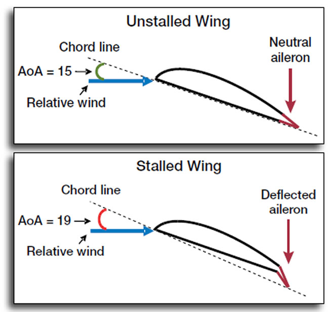
This is an important takeaway. Consider the scenario described in last month’s article: A Cessna 172 performing a short-field takeoff and pitched up to around 15 degrees AoA to climb over an obstacle. In this example, we presume the wing’s critical AoA—the angle of attack at which it will stall—is 17 degrees, two degrees higher than we’re flying. Suddenly, the left wing lowers slightly, and in an attempt to level the wings, the pilot incorrectly positions the stick/yoke to the right to command a right bank to counteract the gust, lowering the aileron on the left (lowered) wing. This control input increases the left wing’s AoA to greater than 17 degrees, resulting in the left wing stalling and rolling left while precipitating a spin in the same direction. The illustrations above show how the wing’s AoA changes with downward aileron deflection. It’s no wonder that continuing to hold the stick/yoke to the right in a futile attempt to raise the lowered wing simply aggravates and intensifies the spin.
But well before we get to stalling a drooping wing, we need to acknowledge the drag-induced performance hit we take whenever we deflect the ailerons from their wings-level, neutral positions. If we’re in that 172 performing a short-field takeoff, we want maximum lift and minimal drag. That’s one reason we’re pitched so high. The last thing we want to do is generate drag, but that’s exactly what an aileron deflection will do, if perhaps only minimally. Regardless of how much or how little drag is created, it’s best to correct a slightly drooping wing with opposite rudder in this situation.
The drag produced when deflecting ailerons is one reason we usually will need to add some nose-up input on the pitch control to maintain altitude. Another reason is the direction change in the airplane’s component of lift. While flying straight and level, the vertical component of lift can be thought of as 100 while the horizontal component’s value is zero. While performing a constant altitude with constant airspeed turn, unless AoA is increased by applying an appropriate amount of nose-up pressure on the pitch control to restore the vertical component of lift to its pre-turn magnitude, altitude will decrease during the turn. The amount of upward elevator pressure applied, and therefore the amount of vertical lift, varies directly with the angle of bank used. As angle of bank is increased, the amount of upward elevator pressure must be increased proportionately to maintain altitude.
Coordinated Turns
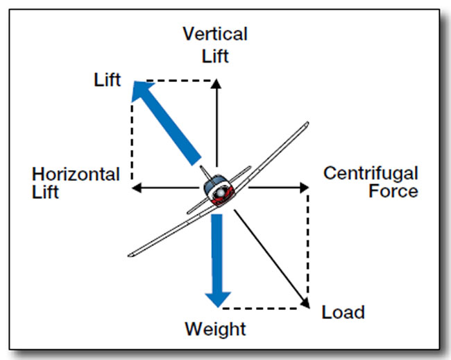
When flying straight and level, the total generated lift is acting perpendicular to the wings and to the Earth’s surface. As the airplane is banked by the ailerons, lift becomes the resultant of two components: the vertical component of lift acting perpendicular to the surface, and the horizontal component of lift—or centripetal (center-seeking) force—acting parallel to the surface. These two lift components act at right angles to each other, causing the resultant total lifting force to act perpendicular to the wings. Also, because part of the vertical lift has been diverted to the horizontal component of lift in the turn, vertical lift is decreased. This is illustrated in the graphic on the opposite page.
The horizontal component of lift turns the airplane. Appropriate rudder pedal pressure in the direction of the turn is needed to keep the ball centered during the turn to produce a coordinated turn. With aileron displacement only, an uncoordinated slipping turn—the slip-skid ball moves out of center “cage” to the inside of the turn—and adverse yaw results. Attempting to improperly turn an airplane by applying rudder pedal pressure only in the direction of the intended turn, and/or applying too much rudder pedal pressure relative to aileron input, results in an uncoordinated skidding turn—the slip-skid ball moves out of the cage to the outside the turn.
A skidding turn results in an excess of centrifugal force (CF) greater than the horizontal component of lift/centripetal force. Centrifugal force acts outwardly on an airplane moving in a curved flight path; it tries to move the airplane away from the center of its rotation. Because CF is increased with a skidding turn—when compared to a properly coordinated turn—wing loading increases and contributes to increases in stalling speed, which predisposes to an accelerated stall.
For example, after takeoff, the nose is pitched up to a high angle, but below critical AoA. Simultaneously, a climbing, 45-degree banked, skidding turn to the right is attempted. The increased wing loading from the steeply banked turn while pitching up, combined with additional loading from the skidding turn, may be enough to induce an accelerated stall. With the slip-skid ball to the left and nose yawed to the right, an inadvertent spin to the right may result. If the airplane’s altitude is too low, no recovery will be possible.
Timing Control Inputs
A question asked by flight students (and, unfortunately, not enough certificated pilots) is: When initiating a turn, what is the proper order to move the flight controls? Should I apply aileron first, followed by rudder, or lead with the rudder? Ultimately, the correct answer depends on the fixed-wing aircraft itself, e.g., its wing, rudder and aileron characteristics may combine to make aileron the lead control. But the usual answer for most aircraft is the acronym “RAE,” pronounced “Ray.” Using it, we apply flight control pressures in the following order: Rudder, ailerons and elevator.
Start or lead the turn by applying an appropriate amount of rudder pedal pressure in the direction of the turn, followed by aileron pressure in the direction of the turn. Then a slight back pressure on the pitch control is added to appropriately deflect the elevator up during the turn.
How much rudder pedal pressure should be applied? Some airplanes fly differently than others. Just enough rudder pedal pressure should be applied to remain coordinated with no adverse yaw. Pilots should not have to stare at the slip-skid ball to make coordinated turns.
Assuming the flight is in visual conditions, the pilot should look outside at the horizon and feel for cues in the “seat of his/her pants” that a coordinated turn is being made. Sitting in the pilot’s seat is like being the slip-skid ball resting on the bottom of the inclinometer in a coordinated turn. During a slip or skid, force pulls both the ball and the pilot’s body out of center of the airplane, the pilot should be able to feel this force reflected by increased pressure by the “seat of his/her pants.” For example, with a skidding turn to the right the pilot would feel the sensation of sideways pressure caused by CF on the left side and bottom of his/her seat.
All Together Now
Many primary students may not fully understand how ailerons function—by increasing and decreasing a wing’s lift—and the drag created as a result. That drag, in turn, creates yawing moments that some aileron designs are engineered to minimize. Thanks to that yaw, and for purposes of perfecting a turn and properly aligning the fuselage during turns, we simultaneously use rudder to fly in a coordinated fashion. Ideally, rated pilots should know this, but many either have forgotten or never were properly training.
One of the keys to understanding ailerons and how they work is understanding the drag they create when deflected (and that they don’t create drag when neutralized). This has implications for stall/spin entry at high AoA, and creates even greater demand for appropriate rudder input. And when performing a banked turn, we use appropriate inputs on all three primary controls—aileron, rudder and pitch—to ensure coordination and prevent altitude loss.
If nothing else, those of us who may be comfortable flying with their feet on the floor in anything other than an unmodified Ercoupe should use this article on ailerons and last month’s on rudder to honestly assess their skills, especially at angles of attack close to the stall.
Dr. Michael Banner is a flight instructor at the University Air Center Flight School in Gainesville, Fla., a professor at the University of Florida and a Civil Air Patrol instructor pilot. He holds the CFI-I and -MEI, has over 5000 hours of flight time and owns a GCBC Citabria.


Interesting blog post. Some tips i would like to bring about is that computer memory ought to be purchased if your computer still cannot cope with everything you do with it. One can put in two RAM memory boards with 1GB each, as an illustration, but not one of 1GB and one with 2GB. One should make sure the car maker’s documentation for own PC to be certain what type of memory is necessary.