
You shouldn’t have gotten through private pilot ground school without understanding that, for the same power and weight, minimizing drag will result in an increased airspeed. A gross example might be the difference in airspeed with flaps extended at, say, 55-percent power and when they’re retracted. Of course, no one cruises with flaps extended, but you may inadvertently be adding to the airplane’s total drag in cruise when you load it.
In a conventional airplane, i.e., one lacking a canard, minimizing the elevator/stabilator’s deflection in cruise reduces drag and can buy you a couple of knots, depending. (The same basic dynamic exists when flying something with a canard—minimize the pitch-control surface’s drag and you’ll fly faster—but we want to talk about what most of us fly.) How much weight to place aft and thereby minimize elevator/stabilator deflection depends on the airplane and how other items are loaded, of course, and you must always stay within CG limits. But if you can easily and safety manipulate your CG, you can go faster.
A Quick Review
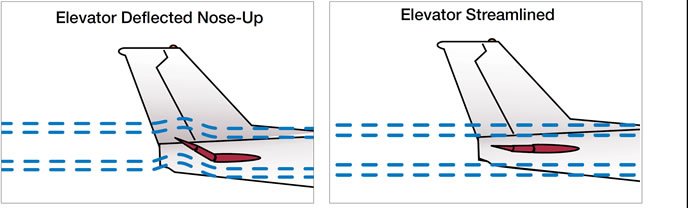
The diagrams below illustrate the basics: By minimizing the elevator/stabilator’s deflection into the slipstream, drag also can be minimized. Because our airplanes need to accommodate different loadings of people and property, among other related characteristics, engineers design their tails with enough downforce to balance the nose-down pitching moment created by the CG being located forward of the center of lift (CL). The tail’s downforce, of course, acts to pitch the nose up. Without it, the nose would pitch down uncontrollably.
With it, however, everything flies nice and level, presuming the tail is generating enough downforce. That’s where the elevator/stabilator comes in, allowing us to moderate how much downforce is generated. By doing so, we control the airplane’s pitch attitude, commanding climbs and descents, but also straight-and-level.
But some of elements of the downforce the tail generates is out of our control. Just as the wing produces lift based in part on its angle of attack and in part on the relative wind’s velocity, the same is true for the tail’s horizontal portion. For example, an airplane may suffer pronounced loss of pitch authority as it slows (e.g., Piper’s T-tail Piper Arrow IV) while gaining it back as it accelerates. Deflect the elevator/stabilator too far at too high an airspeed, meanwhile, and we’ll get a lesson on what it means to exceed maneuvering speed.
In addition to the drag a deflected elevator/stabilator creates, the downforce produced generates drag. That’s as it should be, since we can’t create lift with an airfoil without also creating drag. How much drag is created by the horizontal tail’s downforce is governed by the same math as the lift a wing generates. They all are airfoils; the horizontal tail is simply mounted upside down, to generate its lift downward, not upward. Incidentally, that’s one of the arguments in favor of a canard: since its lift is generated upward along with the wing’s, some efficiency is gained when compared to a conventional wing/tail layout.
In Position
While pilots have direct control of the elevator/stabilator, we neither know nor can do much about its exact angle of attack. We or the autopilot constantly adjust the elevator/stabilator—perhaps through the trim system—to control the airplane’s pitch attitude. In conjunction with power settings, we thereby determine altitude, speed and host of other variables. It’s rather organic, and we really only care that the elevator/stabilator is effective throughout the airplane’s flight envelope and is still there when we land.
Until we want to go as fast as possible for conditions, that is. To do so, we need to streamline the elevator/stabilator as depicted on the previous page, minimizing both the induced drag (a byproduct of the lift being generated) and parasite drag (created when the elevator/stabilator is deflected) and maximizing speed. But there’s a problem: To maintain a level flight attitude, the horizontal tail may be generating an inappropriate amount of lift; either too much or too little. In either case, it’s slowing us down.
Enter the relationship between the airplane’s center of gravity (CG) and its center of lift (CL). Any aircraft moves about its CG, and if an airplane has a conventional tail (i.e., does not have a canard), the tail’s downforce pivots around that CG just like all the other forces. Although the tail normally is thought of as keeping things in balance along the longitudinal axis (the pitch axis), it’s actually forcing the airplane to pivot about the CG: Relax back pressure on the pitch control, and the nose drops as downforce decreases. Increase that back pressure, and the nose rises. Both times, it’s pivoting around the CG.
Balancing Act
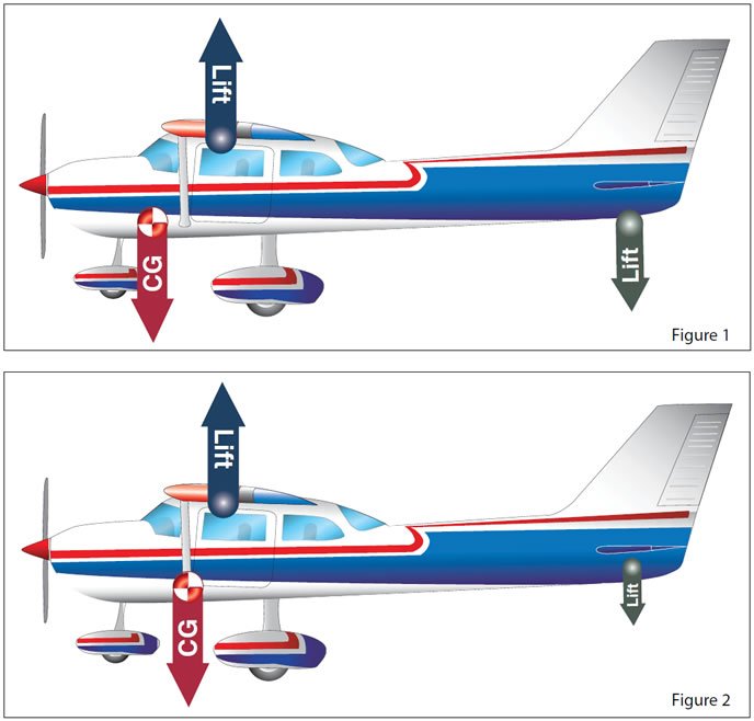
It’s all something of a balancing act, complicated by a variety of factors, but one of the most salient is CG’s location relative to CL. Again, with conventional airplanes, CG is forward of CL. The closer CG is to CL, the less stable the airplane is in pitch and less downforce is required to maintain level flight. Figure 1, at left, illustrates the relationship between CG, CL and the tail’s downforce. Essentially, as long as the CG is where it’s supposed to be—forward of CL—some downforce is required for stability.
Of course, the tail acts as a lever. As an example, let’s say 10 pounds of force way out back on the tail is required to maintain level flight. If the fuselage were longer, only five pounds may be needed. Shorten it, and you’ll need more than 10 pounds.
But we can shorten the distance between CG and CL. We normally can’t do much about changing the CL’s position, so we move the CG, aft in this case. We’ve depicted the results in Figure 2. Notably, we’ve drastically reduced the green downward-directed lift vector at the tail to depict how less downforce will be required to maintain level flight even though the blue upward-directed lift vector and the red weight (CG) vector remain the same.
By now, the lightbulb over your head should be at its brightest setting because we’ve just described how moving the CG aft can reduce the need for downforce from the tail while everything else—gross weight and lift generated by the wing among them—remains the same.
Another way to visualize all this is to imagine a see-saw with two 50-pound children on each end, equidistant from the pivot point. If one child moves forward toward the pivot, his or her end of the see-saw will rise while the other end will drop. To put things back in equilibrium, either the other child also must move toward the pivot, or the first child has to move back to where he or she was seated.
Yes, when it comes to weight and balance, our airplanes are little more than a playground toy. When everything is in equilibrium, much less force is required to lift or lower one end but when weight is shifted away from the pivot point, that changes.
Redistribution
It should be obvious by now that the least downforce will required from the tail when CG and CL are as close as they can be while remaining within the approved envelope. It also should be obvious that instability about the airplane’s pitch axis results from placing the CG and CL close together.
Conversely and equally obvious should be the results when CG and CL are spread further apart: All things again being equal, greater downforce will be required to maintain level flight. For the tail to generate greater downforce, it either has to go faster—not likely—or establish a higher angle of attack. That’s accomplished by deflecting the elevator/stabilator appropriately.
Redistributing items aboard the airplane—luggage, people, anvils—obviously can have an effect on the way the airplane flies. Too far forward and the tail must generate additional downforce. Stability also will suffer by becoming greater and in some airplanes make it difficult to get the nose up in the landing flare. A Cessna 182 with only two people aboard is notorious for requiring extra care and attention in such loading situations.
On the other hand, short-body Beech Bonanzas—Models 33 and 35—are relatively easy to load beyond aft CG limits. According to the FAA’s Pilot’s Handbook of Aeronautical Knowledge (PHAK), FAA-H-8083-25A, “Generally, an aircraft becomes less controllable, especially at slow flight speeds, as the CG is moved further aft.” The PHAK goes on to summarize what we’ve been talking about: “Theoretically, a neutral load on the tail surfaces in cruising flight would produce the most efficient overall performance and fastest cruising speed, but it would also result in instability.”
What does all this mean? Well, for one thing, you now know more about why an aft CG can allow you to eke out a couple more knots of cruise speed, and why the airplane might feel a bit less stable in the bargain.
Figuring out how much weight you can move aft to lighten the tail’s load is relatively easy. Just prepare the weight and balance data as you normally would. Then work the math problem backward by determining how much further aft, within the envelope of course, the load can be placed. Then some more math: How much weight—which items—can you reasonably place further aft in the cabin or baggage compartment to reach the desired position? Be sure to determine the CG after the expected fuel burn, especially when nibbling at the aft edges. Finally, it might be fun to fly some test flights with forward, middle and aft CG locations. plus different power settings, to demonstrate why you might want some weight in the back.


