
Over the last couple of years, I’ve spent some time helping students transition to full-fledged private pilots. One of the first questions I do is ask them is to picture a standard six-pack of “steam-gauge” instruments and explain what they each do and where they get their energy. Most pilots can quickly rattle off the airspeed indicator, the altimeter and the vertical speed indicator. Those systems are relatively simple to understand and describe.
The gyros, however, seem more challenging for students. I have always maintained that, to understand the gyroscopic instruments better, it is best to hold one in your hand, where you can observe how it operates, especially when the case has been removed. Seeing the buckets, gimbles, motors and other components up close demonstrates these concepts so much better than a verbal or written description, or even a photo.
The next task is usually to correct the commonly held belief that the airplane’s static system is somehow connected to its vacuum system. (Yes, both systems use air, but in different ways.) Then we review the electrically powered instruments. A further confusion that I find with students (and even some private pilots) is where and how the vacuum is generated. Without understanding the vacuum source and how it works, a pilot is unlikely to have an accurate understanding of the common causes of failure and how a failure can be resolved.
Quick Review
Unless you’ve only flown a glass-panel aircraft, you likely recall a standard six-pack of flight instruments traditionally includes three gyros. These are the attitude indicator (AI) and the heading indicator or directional gyro (HI/DG), plus the turn coordinator (TC) or turn-and-bank indicator (T&B). Of these, the AI and HI/DG traditionally are powered by vacuum. The TC and T&B traditionally are powered by the aircraft’s electrical system and worthy of their own article. Let me stress that this is the traditional configuration; the actual power sources can and often do vary from aircraft to aircraft.
One example of variations is the HI/DG. I have seen a number of aircraft equipped with a horizontal situation indicator (HSI), and in every example the instrument gets its energy from the electrical system. (The HSI is far superior to a DG, but if you don’t realize it has a different energy source, the need for that knowledge may come to you at an inopportune moment.)
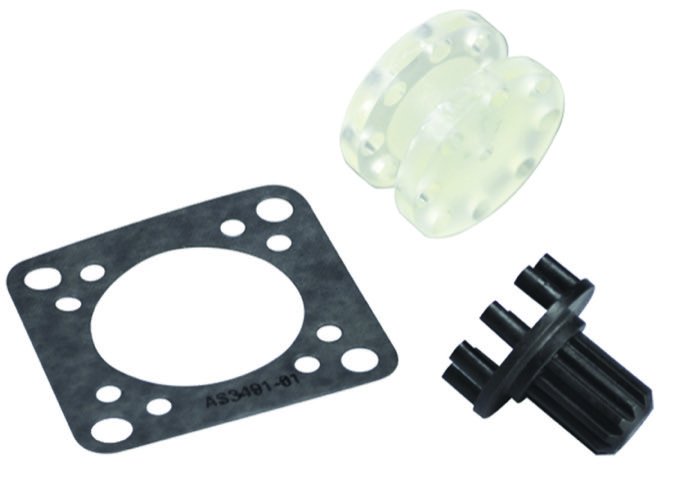
By far, the most common vacuum source is an engine-driven pump. These come in two basic flavors, a so-called “dry” pump and a “wet” one. The difference speaks to how they are lubricated internally: A dry pump turns a set of carbon/graphite vanes, which are self-lubricating. A wet pump uses engine oil for lubrication of its metal parts and usually employs an air/oil separator to remove excess air from the oil before it’s returned to the engine’s lubricating system, to prevent foaming and minimize contaminants in the engine.
The different types of pumps will have different failure modes. For example, a dry pump’s vanes wear and may suddenly fail and break apart. This not only prevents the pump from creating vacuum but also may jam it and prevent further rotation, shearing the drive shaft (more on this in a moment). Dry pumps may not be economical to rebuild, at least in the field, and often are considered throw-away items.
Wet pumps, on the other hand, tend to fail more slowly, giving you more time to address the failure. Wet pumps can be overhauled, and they typically are removed only when the engine to which they’re mounted is replaced or sent out for overhaul. They usually are heavier than dry pumps, but not overly so, and their installation is more complex, thanks to the need for additional oil lines and an air/oil separator.
Mounting And maintenance
Regardless of which type your airplane has, both are mounted to the engine’s accessory case. They are driven by the gears within the accessory case, which also are used to turn the magnetos and/or other components mounted there. A shearable driveshaft is used to protect the accessory case and the rest of the engine in the event the vacuum pump suffers a failure resulting in greater-than-normal friction or sudden stoppage.
In the event the pump’s load exceeds the shaft’s strength, the shearable shaft (as the name implies) breaks, permanently disconnecting the pump from the engine. This has the very desirable effect of protecting the engine’s internal components from a failing pump and the less-desirable effect of causing the vacuum pump, with little warning to the pilot, to stop working.
Some dry pumps include an inspection port for a mechanic to check the vanes to ensure they continue to meet the manufacturer’s minimum return-to-service values. It’s a good idea to request this type of pump when replacing one and to make the port part of the aircraft’s regular inspections.
There are two outlets on the pump: one supplying positive pressure and one providing the vacuum. For most light GA aircraft, the positive pressure outlet is not used and, in fact, may not be connected to anything more than a piece of hose. Other airplanes may exclusively use the pressure outlet instead of the vacuum. In such installations, the pressure side may be used to perform other tasks in addition to turning some gyros, most notably to inflate wing- and tail-mounted deicing boots. Such aircraft mount gyros adapted for use in a pressure system instead of one supplying vacuum. Systems relying on pressure instead of vacuum tend to use larger pumps and may employ two or more of them, especially when considering piston-powered twin-engine airplanes. Pressure systems, especially those used in conjunction with deicing boots, tend to be dry pumps exclusively, since the fine oil-laden mist that’s an inevitable byproduct of a wet pump isn’t compatible with the rubber used in the boots.
The pump itself is not the only component of a vacuum system. The vacuum pumps used are of a constant displacement design, which means they will move a constant amount of air every time the pump turns a complete revolution. You may already have spotted the problem: As the engine changes speed, the amount of vacuum generated will vary. To address this situation, the system includes a regulator that keeps vacuum levels within a stable, preset range. It, too, can fail.
Backing It Up
To guard against vacuum failures, there are number of standby emergency and redundant systems available. Perhaps the most popular is to simply install a dual-pump system. These systems equip an aircraft with two vacuum pumps that run simultaneously, both feeding the same vacuum regulator. This configuration is common aboard piston twins and may also be found on singles when the engine’s accessory drive allows for mounting the second pump. Since these pumps run continuously, they will wear at approximately the same rate. It is a good idea to consider replacing both when needing to replace one. The aircraft should have an indicator to alert the pilot if either or both pumps have failed.
Some aircraft are equipped with a standby electrically driven vacuum pump. If the pilot determines the primary vacuum has failed, they have the option to engage the standby pump mid-flight. This redundancy requires the pilot to recognize that the primary pump has failed, and to take action. There will be an annunciator showing the state of the primary pump, and whether the standby pump is active or not.
Another type of emergency system connects the vacuum lines to the engine’s induction manifold via a valve. After the pilot determines that the primary system has failed, the pilot can open the valve to change the vacuum source from the pump to the engine’s intake manifold. This system depends on the differential between ambient pressure and that present in the intake manifold to create enough vacuum to spin the gyros. It also comes with a caveat.
Since the system depends on the difference between ambient pressure and manifold pressure, that difference must be on the order of four or five inches of mercury (Hg), the nominal value needed to spin the gyros. That’s fine when you’re tooling around at a relatively low altitude and power setting, but might not be sufficient at higher altitudes.
Say you’re flying a normally aspirated (i.e., non-turbocharged) airplane at 10,000 feet msl. At full throttle, the engine is making maybe 20 inches of Hg, which is approximately the ambient pressure, also. To generate the 4-5 inches of differential the gyros like, you’ll need to reduce power to around 15 inches of Hg, which may not be sufficient to maintain level flight. You’ll have a choice: spin the gyros faster or spin the prop faster. Clearly, such a system should not be considered fully redundant but only as a way to keep the shiny side up long enough to divert to the nearest airport, preferably one with a mechanic and a new vacuum pump.
Another way to back up your vacuum system is to install redundant instruments, like an electrically driven AI. Thanks to modern technology, such instruments are not only relatively inexpensive, they can provide a great deal more functionality than the steam gauge they’re backing up.
The Ultimate Fix
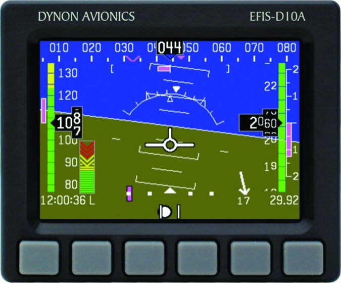
Perhaps the ideal way to prepare your airplane for a vacuum failure is to remove the system altogether and go all-electric. We have the technology—both in conventional electric gyros and all-electronic devices like Garmin’s G5 instruments or Dynon’s EFIS-10A—to eliminate the vacuum system entirely and depend on either self-contained batteries or redundant electrical systems to ensure we’ll always have a working system that tells us which way is up. See the sidebar on the opposite page for a summary of options to prepare for the day (or dark and stormy night) when your vacuum system stops sucking.
Although handling a partial-panel emergency (i.e., when part of your panel-mounted instruments fail along with the vacuum system) is beyond this article’s scope, see the sidebar above for a brief description of what you might expect. If you’re on instruments in IMC, it’s time to put all that partial-panel practice to work. If you’re in VMC (and especially if in IMC), cover up the failed instruments with whatever’s available. At a minimum, force yourself to disregard their indications. Vacuum systems generally work well, until they don’t. There’s no substitute for understanding how they can fail.
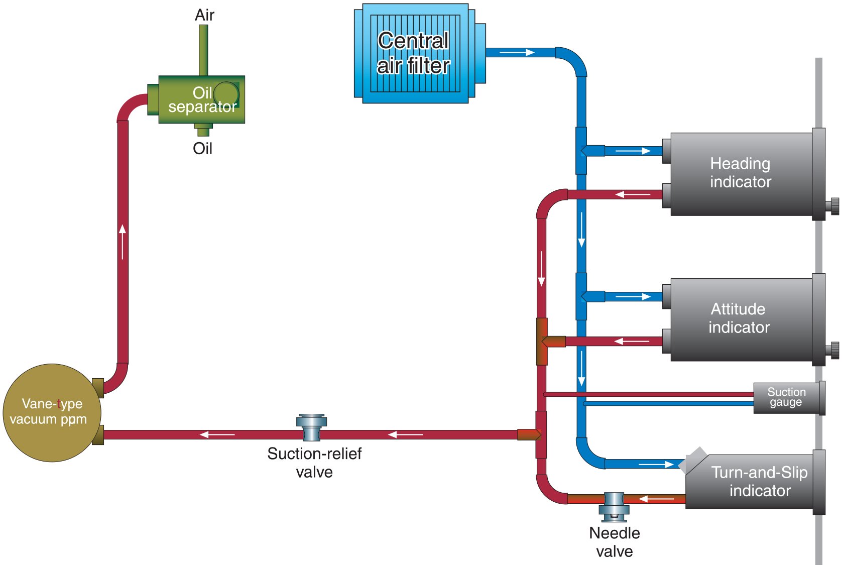
The typical vacuum system in a piston single will closely resemble the one described in the schematic at right, which features a “wet” or oil-lubricated pump. Variations include dual-pumps aboard twins, and a single-engine airplane may be equipped with some sort of backup system.
• The pump creates negative pressure at the filter, allowing ambient air to enter the system.
• That air flows into each vacuum-driven instrument and to the system gauge independently, then to the pump.
• The air sucked through each instrument spins a gyroscope, providing a stable reference against which to compare the airplane’s attitude and heading.
• A regulator controls how strong the vacuum is, with excess vented overboard.
• A dry vacuum pump, which uses self-lubricating graphite-based vanes, will not incorporate an air/oil separator.
Backup And Standby Vacuum Options
If you spend much time flying a steam-gauge panel using vacuum-driven gyros, it’s usually a matter of when you’ll suffer a failure, not if. And if your time often is spent in instrument conditions, a vacuum system failure quickly can become a full-fledged emergency instead of a mere inconvenience.
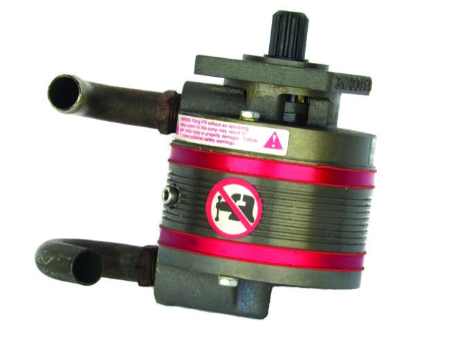
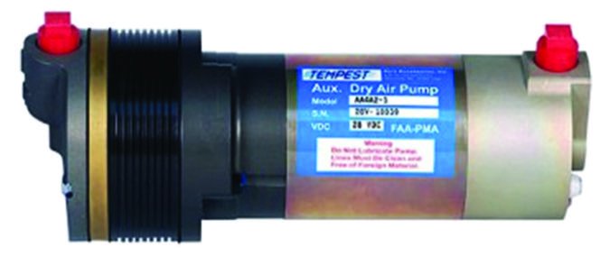
Presuming you can’t install all-electric replacements for your vacuum-driven gyros, you might want to consider some kind of backup system. Some examples include an electrically driven vacuum pump, like the one from Tempest at upper right.
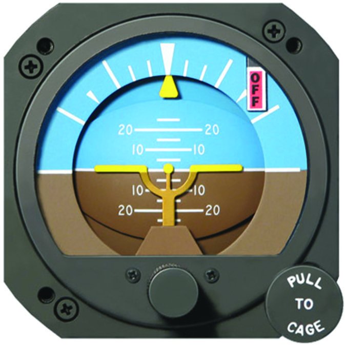
If you have the panel space, installing a backup gyro of some sort might be just the ticket. Among its other products, R.C. Allen makes electric artificial horizons like the one at middle right, plus an all-electronic device, at bottom right. Backup instruments like these are relatively simple to install, needing little more than a vacant instrument hole and a dedicated circuit breaker. As a minor alteration, they typically will not require more than a simple logbook entry when it comes to paperwork.
Meanwhile, recent changes in the FAA’s regulatory stance on all-electronic instrumentation has resulted in products like the Garmin G5 and the Dynon EFIS-10A (below). These are full-fledged gyros that can be installed as primary instruments in certified aircraft with the right paperwork from their respective manufacturer. An all-electronic replacement for your vacuum-driven gyros offers more options and capabilities than a backup-only instrument, so installation will be more involved. If you plan to use them as primary instrumentation aboard a certified aircraft, you’ll need a version that comes with an STC.
Recognizing A Vacuum System Failure
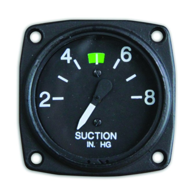
The word most often used to describe a vacuum system failure is “insidious.” That’s because the typical airplane using a vacuum pump to spin its gyros lacks a system to alert the pilot that the vacuum isn’t vacuuming any more. Yes, there’s probably a small gauge indicating the system’s vacuum in inches of mercury, but it’s usually not in the pilot’s regular scan. When it’s finally noticed, the failure may have gone undetected for many minutes.
Meanwhile, as the vacuum-driven gyros (AI and HI/DG) spin down, they’ll begin reacting sluggishly. One or both will begin to drift from their normal indications. The DG/HI will present a slow heading change and the AI may indicate a bank and/or pitch change, even if no other instruments do. Eventually, the DG/HI will start spinning slowly, and the AI will adopt a steady tilt.
There’s a safe and sane way to educate yourself on what a vacuum failure looks like. After shutting down at the end of your next flight in an airplane with vacuum-driven instruments, stay seated. Listen to the gyros spin down, and watch what the AI and DG/HI do. They’ll react pretty much the same in flight.
When the vacuum system fails, the AI and the DG/HI may start indicating a bank and a heading change together, leading the pilot to conclude they are correct and there’s some other problem. Following the indications of a failed gyro rarely has a good outcome. This is when your instrument scan must be used to compare them with other instruments to determine what’s going on. — J.B.
James Warmkessel holds FAA flight, instrument and multi-engine instructor certificates, and is an A&P-IA. He’s also an aviation podcaster and IT professional living in the San Francisco area. Follow his podcast at www.avstry.com.


