
After 20 years as a flight instructor, I’ve observed that too many general aviation pilots do not monitor nor understand the significance of maintaining cylinder head temperature (CHT) within the proper operating range. Thanks to aircraft system ignorance, failure to maintain engine situational awareness, laziness, apathy or combinations thereof, many pilots are remiss at monitoring CHT, an essential engine parameter. Why should pilots be concerned about maintaining CHT within the proper operating range?
In his book Proficient Pilot (Vol. 2), Captain Barry Schiff states: “Heat is one nemesis of a piston engine airplane. Its cumulative effects can lead to piston, ring and cylinder head failure, as well as placing thermal stress on other engine components.” Abnormally high CHTs in normal operation weaken the aluminum alloy from which cylinder heads are manufactured. High CHTs over protracted periods can result in serious engine damage and failure.
CHT DEFINED
Cylinder head temperature mainly reflects what is going on during the engine’s power stroke before the exhaust valve opens. It is a measurement of heat energy during the power stroke when the cylinder is under maximum stress from high internal pressures and temperatures.
High CHTs indicate the engine is under excessive stress. Because CHT is the best proxy the pilot has for assessing internal cylinder pressure—which represents stress on the engine—it is an important reference when adjusting power and mixture settings. The pilot should use the engine controls and cowl flaps, if any, to maintain no more than a target CHT representing the maximum stress they want the engine to endure, and a good place to start determining that target CHT is the airplane’s operating limitations. To keep the engine within its normal operating parameters, CHT needs to be controlled by timely and appropriate pilot interventions.
Combustion within the engine generates a substantial amount of heat, much of which is expelled via the exhaust system. However, a large amount of heat energy remains, and it must be removed to prevent the engine from overheating. If not, very high engine temperatures, primarily measured as CHT, can lead to loss of power, excessive oil consumption, detonation and significant engine damage. An engine’s oil system provides for some internal cooling of the engine, also, but it’s incapable of meeting its entire cooling needs. The oil temperature gauge provides an indirect and lagging indication of increasing engine temperature; it may be used for inferring engine temperature if CHT is not available or as delayed confirmation if it is.
COOLING
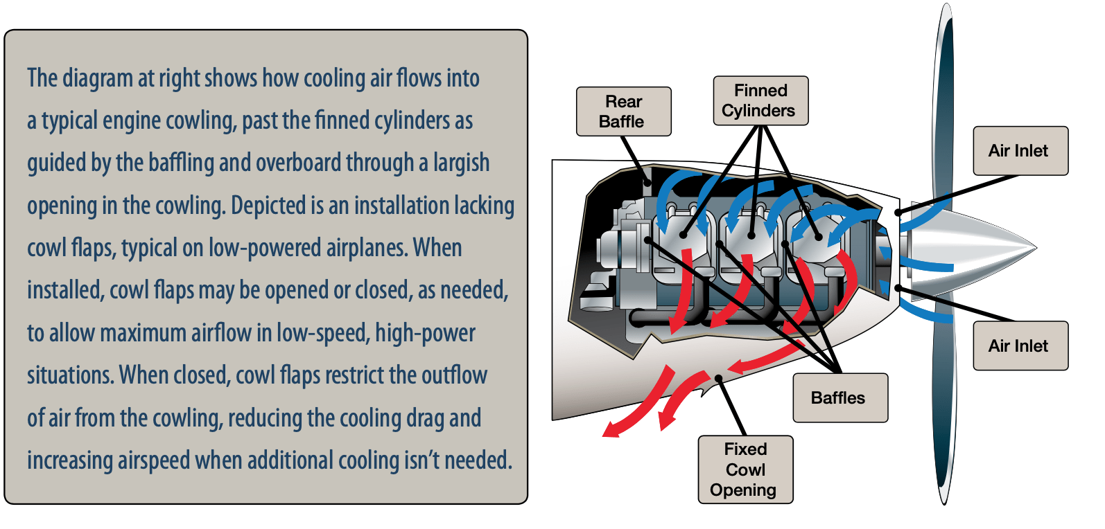
Since the lubricating system isn’t up to the task, an additional method of cooling is required. The typical piston engines we fly behind or between are air-cooled. Air-cooled engines primarily rely on outside air flow directed into the engine compartment through openings in the engine cowling for cooling. Baffles within the engine compartment route incoming air over fins attached to each cylinder and perhaps through an oil cooler to dissipate the engine’s heat. The hot air exits through one or more openings at the rear of the engine compartment.
Some aircraft employ cowl flaps to help control air flow through the engine compartment and, in turn, engine cooling. Cowl flaps are small doors that may be opened or closed from the cockpit, typically with a manually operated push-pull cable. Cowl flaps may be closed for cruising and higher airspeeds, and opened partially or fully for takeoff or climb operations, when power output is higher and cooling air flow is lower. By fully opening the cowl flaps, a larger path for the hot air to escape from the engine compartment is created, thereby increasing cooling airflow but also increasing cooling drag.
Liquid-cooled aircraft piston engines also exist. As the term implies, a coolant is pumped around the cylinders, drawing off heat, and then through a radiator to cool the liquid before it’s recirculated. Engines like the Rotax 912UL incorporate a hybrid design combining liquid-cooled cylinder heads with air-cooled cylinders. Liquid cooling systems typically result in more uniform operating temperatures, thanks to their thermostats, but often result in heavier engines of similar displacement and power output. Cooling with air isn’t as uniform, but it saves weight and eliminates the possibility of coolant leaks.
TOOLS FOR MANAGING CHT
Air-cooled engines with controllable cowl flaps typically have a tighter-fitting cowling and higher-output engines. Because cowl flaps restrict cooling airflow in favor of reduced drag, they must be open when air flow is reduced, like during ground operations, takeoffs and climbs, go-arounds/rejected landings and other high-power, low-airspeed operations, especially when ambient temperatures are high.
Another way to manage CHT is with fuel. A rich mixture allows fuel in excess of that required for engine operation results in a cooler combustion event, reducing the heat that needs to be dumped overboard. Running a rich mixture can get expensive, though, isn’t efficient and likely will result in excessive fuel burn, reducing range and endurance.
Engine heat management with the mixture control often is referenced with exhaust gas temperature (EGT) and how close or far away EGT is to its peak. Peak EGT at high power settings—more than 65 percent of an engine’s rated power—is to be avoided because it’s where internal pressures and the potential for engine damage are at their greatest.
The good news is that once we lean past peak EGT toward the other end of the mixture spectrum, the combustion event isn’t as hot. Leaning the mixture past peak EGT—termed “lean-of-peak” or LOP—results in slightly less power but a relatively large reduction in CHTs and reduced fuel flow. Lean-of-peak operation also may be used at high power settings, as long as the mixture is leaned far enough beyond peak EGT so that high internal pressures are avoided and CHTs run cool.
Some airplanes do not have controllable cowl flaps, instead employing a fixed opening on the engine cowling for hot air to exit the engine compartment. If neither cowl flaps or LOP operation are available, reducing the airplane’s pitch attitude and increasing airspeed also boosts the ram air flow into the engine compartment for better engine cooling. Enrichening the mixture also helps. Other options include reducing engine power, stopping a climb and leveling off to increase the flow of air into the engine compartment.
Much of any discussion of CHT management centers on reducing heat; there’s often not enough talk about avoiding abrupt or “shock” cooling. According to Lycoming, “Sudden cooling is detrimental to the good health of the piston aircraft engine.” The company recommends a maximum temperature change of 50 degrees F per minute. In normal operations, pilots don’t get into situations where a 50-degree/minute reduction in CHT occurs, thereby eliminating any possibility of “shock cooling.”
Nevertheless, Lycoming recommends avoiding fast letdowns with very low power (high-cruise RPM and low manifold pressure), along with rich mixtures. “It is recommended that pilots maintain at least 15” MP or higher, and set the RPM at the lowest cruise position,” the company says. “This should prevent ring flutter and the problems associated with it.”
“The mixture should be left at the lean setting used for cruise and then richened gradually during the descent from altitude,” Lycoming continues. “The lean mixture, maintaining some power and using a sensible airspeed should achieve the most efficient engine temperatures possible.”
OPERATING LIMITATIONS
Pilots always should take the time to read through the aircraft’s POH/AFM and follow the manufacturer’s guidelines for maintaining CHT in the proper range during all phases of flight. For example, the POH for a Cessna 182T Skylane with a Lycoming IO-540 six-cylinder, horizontally opposed, air-cooled, fuel-injected engine states that throughout takeoff and high-power climb operations, the cowl flap lever should be placed in the fully “open” position to promote maximum engine cooling to maintain CHT in the normal range (200 to 500 degrees F, which is way too high an upper limit, in our opinion).
Regarding cruise flight, the POH also directs the following: “While in cruise flight, cowl flaps should be opened or closed as needed to keep CHT at approximately two-thirds of the normal maximum operating range,” implying a target CHT of approximately 350 degrees F should be maintained.
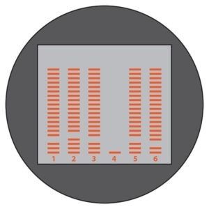
Although presentations may differ from instrument to instrument, multi-probe engine monitors and engine information systems all work basically the same way: A bar graph shows each cylinder’s relative EGT values with stacked horizontal bars. The absence of a bar for a cylinder denotes its CHT. Let’s interpret some typical indications, and start with an easy one.
At right, monitor A shows no EGT and very low CHT readings on cylinder #4. Presuming the EGT probe and its wiring are sound, this likely indicates a clogged fuel injector on injected engines, or a somewhat major ignition or mechanical problem.
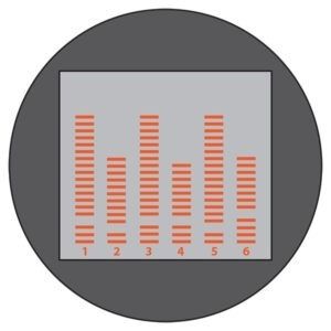
Monitor B, shows cylinders #2, #4 and #6 with reduced EGT values and cylinder #6’s CHT is slightly elevated. Since these cylinders are on the same side of the engine, the problem may be extensive blockage of the induction or fuel supply system. There also may be a baffling or foreign object problem affecting #6’s cooling.
Since EGTs rarely are uniform among all cylinders, Monitor C shows a relatively normal display, except for cylinder #3’s CHT. Again, cooling baffles or a foreign object may be at fault.
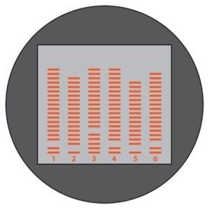
There are a host of different ways to use an engine monitor, including during magneto checks and in diagnosing other potential engine problems. These three examples are relatively simple but show how useful the devices can be.
CHT INSTRUMENTATION
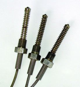
Real-time CHT data can be obtained, measured and displayed on the instrument panel by installing a sensor in each cylinder. Typical bayonet sensors are pictured at the top of the opposite page. The gasket sensor, installed between the spark plug and cylinder head, is another CHT sensor type, although it’s considered not as accurate as the bayonet probe.
Airplanes with legacy instrumentation typically provide CHT information for one cylinder only. This is a considerable limitation, as some cylinders will be hotter than others and the probe might not be installed in the hottest cylinder. Each cylinder needs to have its own CHT sensor.
Combining CHT data with EGT for each cylinder provides valuable engine operating information to the pilot. As with CHT, EGT is measured by a probe, in the exhaust system this time, of each cylinder’s exhaust. An EGT indication means combustion is occurring in the cylinder and how hot it is. Since EGT can change much more quickly than CHT, it’s preferred over the latter when we want to know how the engine is reacting to adjusting the mixture.
Modern operating techniques generally call for rich mixtures at high power settings to help keep CHTs within limits. In cruise flight and depending on the power settings, lean-of-peak EGT operation is becoming the norm for well-instrumented airplanes with induction systems that support it. It’s important to understand the relationship between EGT and CHT because together the two are invaluable for detecting and diagnosing engine abnormalities.
USING CHT
Monitoring CHT is essential to help protect the engine from thermal stress, ensure cylinder longevity and prevent in-flight engine failure. It’s the best proxy we have to detect high internal cylinder pressures. Pilots should also understand how to make proper interventions to appropriately manage CHTs.
Michael J. Banner PhD is a flight instructor in Gainesville Fla., a courtesy professor at the University of Florida in Gainesville and check/instructor pilot for the Civil Air Patrol. A CFII and MEI, he has 6100 hours flight time and owns an American Champion Citabria.


Thanks for sharing this article. Steering on the ground is achieved by turning the nose wheel, either by a tiller wheel in the cockpit or by using the rudder pedals. When taxiing, aircraft move slowly to reduce the risk of nose wheel damage. A slow speed also ensures a quick stop if necessary