
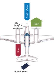
For the most part, flying a multi-engine airplane is just like flying a single. Until an engine fails. When transitioning from a single to a conventional twin, pilots spend most of their training learning to handle engine failures and to eke out what little performance remains. In conventional twins we’re likely to fly, that means understanding the aerodynamics that require zero sideslip, obtaining and maintaining the best single-engine rate of climb speed and demonstrating the minimum control airspeed—shortened to either VMC or VMCA (we’ll use VMC in this discussion). The graphic below provides the FAA-approved definitions for these terms.
One of the things transitioning pilots learn is that the published minimum control airspeed (VMC) is fixed for a specific set of conditions, including airplane weight and atmospheric conditions. It’s represented by the red radial line on the airspeed indicator. But the actual VMC varies with weight and atmospherics, plus other conditions. In practice, the difference between the published and actual VMC for when you lose an engine is critically important. To better understand why, let’s first discuss the published VMC number.
The FAA’s AC 23-8C, Flight Test Guide for Certification of Part 23 Airplanes, provides information of great interest to pilots and includes some eye-opening statements. For example, the AC states: “There are variable factors affecting the minimum control speed. Because of this, VMC should represent the highest minimum airspeed normally expected in service.” However, “normally expected in service” is a little misleading.
Paragraph 4b(3) of the AC points out that banking into the good engine is allowed (all experimental flight test pilots certifying a new twin will do this because it lowers the VMC and reduces drag). Also, paragraph 4b(1) states that maximum aileron deflection can be used to obtain the bank angle.
Remember that at the lower airspeeds the ailerons will be less effective and countering the torque of high horsepower engines. It may require full aileron deflection to establish a small bank angle into the good engine and the AC permits this. Furthermore, paragraph 4b(1) states that maneuvering may not be possible at VMC. Read that again.
PUBLISHED VMC
The published VMC is primarily determined by the amount of torque developed by the operating engine, and the size of the vertical stabilizer and rudder to oppose the torque. However, other conditions also play an important role in determining VMC. Bank angle has a large but often unappreciated role, as does the weight of the airplane.
When designing their twin, aeronautical engineers make trade-offs or compromises. They and the marketing team would like to have high-horsepower engines for speed and as small a vertical stabilizer for weight savings and reduced drag. However, this combination of high torque and small vertical surface area increases the minimum control airspeed. To help the designer, the FAA airplane certification requirements allow a bank angle of up to five degrees toward the good engine, an attitude that lowers the VMC.
Conversely, to make the certification conditions closer to the worst case, the VMC tests are performed at an aft CG, low weight, a windmilling propeller on the failed engine (unless the airplane has autofeathering) and maximum power on the good engine. It should be noted that the low weight is only a penalty if it is in conjunction with a bank into the good engine. A heavier airplane results in a higher VMC when banking into the dead engine.
To be knowledgeable about asymmetric-powered flight, the multi-engine pilot should be familiar with the airplane certification requirements, which may be found in FAR 23.149 (superseded in 2017 by FAR 23.2135). The old FAR 23.149 provides more detailed regulatory guidance. However, Advisory Circular 23-8C, Flight Test Guide for Certification of Part 23 Airplanes, provides experimental flight test pilots the recommended methods to demonstrate the certification requirements. The sidebar above includes additional details.
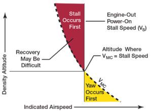
Each light twin’s published VMC is usually marked on its airspeed indicator as a red radial line, but it changes with density altitude and bank angle, among other variables. Specifically, VMC decreases as density altitude increases.
Eventually, it will decrease to or below the airplane’s stalling speed. When the published VMC is less than VS, the FAA recommends artificially limiting rudder authority during the demonstration. Regardless, in no situation should the VMC demonstration proceed to a stall, which may be unrecoverable.
ACTUAL VMC
The actual VMC in flight depends on how you are operating the airplane. It is doubtful that you are flying it as precisely as the experimental test pilot that collected the VMC data. Their data was used to generate the published value. Normally, your actual VMC will be considerably higher.
When you lose an engine you must first maintain or increase airspeed, identify, verify and feather the dead engine. However, there are additional items to maintain control. Did you apply full rudder or enough to stop the heading change? The rudder is the primary control to compensate for the asymmetrical torque. Did you try to maintain wings level or did you establish the favorable bank into the good engine? Remember that maintaining a wings-level attitude will in all cases produce an actual VMC higher than if you are banked slightly toward the good engine. Worse than trying to keep the wings level, are you attempting to make a turn toward the dead engine?
There is an excellent description in a YouTube video “Multi-Engine Training – Part 2 – VMC (Minimum Control Speed)” by Martin Pauly with an excellent discussion of Vmc by Doug Rozendaal. Every
multi-engine airplane pilot should look at this video. I believe pilots get somewhat complacent with the yaw at the start because it begins slowly but once the vertical stabilizer/rudder’s critical angle of attack is reached it’s too late to correct it.
Likewise, Harry Horlings has an excellent YouTube video as well as several technical papers on VMC. He makes an excellent point on the criticality of banking into the good engine, i.e., lifting the dead. I’ve never seen the graphs he presented on the effect of bank angle on VMC and effect of weight and bank angle on VMC. Harry’s information is super, really valuable information that likewise should be reviewed by all multi-engine pilots.
The University of North Dakota Department of Aviation has on-line interactive trainers. One of these trainers is “One Engine Inoperative Aerodynamics.” It shows the advantage of the slight bank into the good engine vs keeping the wings level. If you select the wings level option, the actual VMC goes up as expected.
RUDDER STALL?
To keep the airplane under control you must do several things with deliberate but quick action. Primary among these is the yaw rate toward the failed engine has to be stopped quickly. If it isn’t stopped, the loss of control can happen very rapidly. It can be deceiving because the yaw may seem to start slowly, only to accelerate the longer the yaw rate persists. If the yaw rate persists and the slide slip becomes too great, the vertical stabilizer/rudder can stall and the airplane snap roll into the dead engine.
On October 30, 2014, a Beech B200 King Air crashed during initial climb from the Wichita Mid-Continent Airport (ICT) in Wichita, Kan. The solo pilot was killed and the airplane destroyed when it impacted a FlightSafety International training facility. Three in the building were fatally injured, two occupants sustained serious injuries and four occupants sustained minor injuries. Shortly after liftoff, the accident pilot reported to ATC that the left engine had failed. The NTSB analyzed surveillance video of the accident sequence, calculating that “the airplane’s sideslip angle as captured in the image of the airplane during the last second of flight showed that the airplane had a 29° nose-left sideslip, which would have required the application of a substantial left rudder input.”
The NTSB partially attributed the crash to incorrect rudder application. However, the result of a 29-degree sideslip likely would have caused a vertical stabilizer/rudder stall. Can you imagine a wing with a 29-degree angle of attack and it not stalling? Documentation for the Lockheed C-130T states: “If the airplane is maneuvered to abnormally high sideslip angles (15-20 degrees), a fin stall resulting in large yawing transients and a loss of directional stability can be encountered.”
Unfortunately, if you are at low airspeed, muscle memory is not going to work well to control the airplane in this situation. You cannot practice this in the airplane because it’s too risky. The training that is given nibbles at the edge of the issue but doesn’t give you the ugly experience. In actuality, if an engine fails on takeoff, you must be ready to apply much more yoke and rudder deflection/force than expected and you must be mentally prepared to reduce power on the good engine(s) if required.
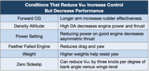
Flying a conventional twin on one engine is not unlike trying to stand on a basketball. Any failure to establish and maintain zero sideslip with the optimal bank angle and rudder input results in a reduction in single-engine climb capability. Meanwhile, conditions that reduce VMC helps you maintain control at slower speeds but also reduce climb performance. The table at right is adapted from the FAA publication “Flying Light Twins Safely” and highlights some of the conditions affecting real-world VMC and performance.
TAKE IT TO THE BANK
As stated, establishing a proper bank is very important when flying a conventional twin with an engine inoperative. The old adage to not bank toward the dead engine applies in spades. As can be seen from the bank angle data discussed previously and in the sidebar above, the actual VMC goes up dramatically once you bank toward the dead engine. At low airspeeds, it will require more than normal aileron deflection to roll toward the good engine. Remember: Raise the dead (engine).
While it is critically important to establish the bank into the good engine, don’t overdo it. Do not go past approximately five or six degrees. As the graph in the sidebar above depicts, banking past five or so degrees away from the failed engine will start increasing drag and introduce an opposite sideslip. This will again increase the chance of stalling the vertical stabilizer/rudder (fin).
Omitted so far from our discussion is coordinating and stabilizing the sideslip with rudder, presuming additional rudder authority remains. For this we use the most underutilized instrument in the panel, the inclinometer or ball. Remember back to your primary training when you were urged to “step on the ball.” In the case of one-engine inoperative flight, leaving the ball half of its diameter out of its “cage” toward the good engine will reduce the overall sideslip and drag.
Along with continually asking yourself “what if?” having a safe flying career requires that your aviation education should not end with initial training. Before advancing power for takeoff, think about what is required if the engine decides to quit at various points during the maneuver. Remember that you have five basic controls to prevent a VMC accident: rudder, aileron, elevator for airspeed control, thrust on the remaining engine(s) and your training. Use all five and you will maintain control when an engine fails. As a bonus, you’ll end up with a great hangar story. Keep learning and keep flying safely.
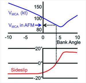
The effect of bank angle on VMC and sideslip when a twin’s left engine is inoperative and the other is at maximum thrust is shown in the graph at right. Using this graph, or one like it, engineers can assess how large or small to design the airplane’s vertical stabilizer for the desired VMC value. In this example, VMC has already been established.
The vertical lines in the center of the graph denote a wings-level attitude, and show a negative bank angle toward the failed engine and a positive one away from it, i.e., when the dead engine is raised. The slanted blue line toward the top of the graph depicts VMC resulting from various bank angles toward and away from the failed engine. The red line depicts the amount of sideslip associated with the various bank angles.
The dotted black line, in turn, shows how zero sideslip is achieved at an approximate four-degree bank. Under FAA requirements, no more than a five-degree bank is allowed when demonstrating VMC for aircraft certification purposes.


