
Most of us fly aircraft powered by piston engines, a basic technology dating back to the late 19th century. Meanwhile, the modern air-cooled aircraft piston engine’s basic configurations hasn’t changed since before WWII. Given the power output for their weight and fuel consumption, there’s no better solution. But hundreds of metal parts going through thousands of heat cycles year after year eventually find a way to break. When it happens, we’re trained to safely get the airplane on the ground. Most of the time, that’s exactly what happens. In fact, there are no real data on general aviation engine failures except those resulting in a reportable accident.
Many such failures result in a safe landing, because they occurred near an airport or there was another engine available, say, on the other wing. One could examine new and used parts sales, plus records for new and remanufactured engines, and overhaul shop activity, but—lacking exposure data associated with number of flights and hours flown—even that won’t provide a full, clear picture of the engine-failure rate. Regardless, one of the weak links in the chain that is the typical aircraft piston engine is its cylinders.
How Do Cylinders Fail?
Aircraft piston-engine cylinders have three basic failure modes. They involve the intake and exhaust valves, general cracking at various locations on the cylinder and head/barrel separation.
Cracks
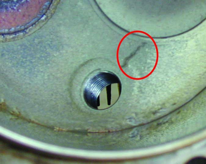
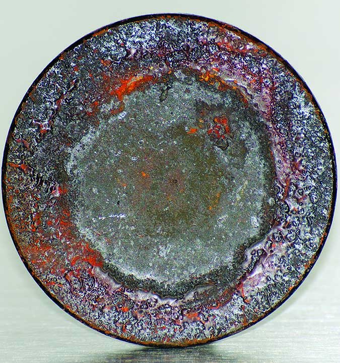
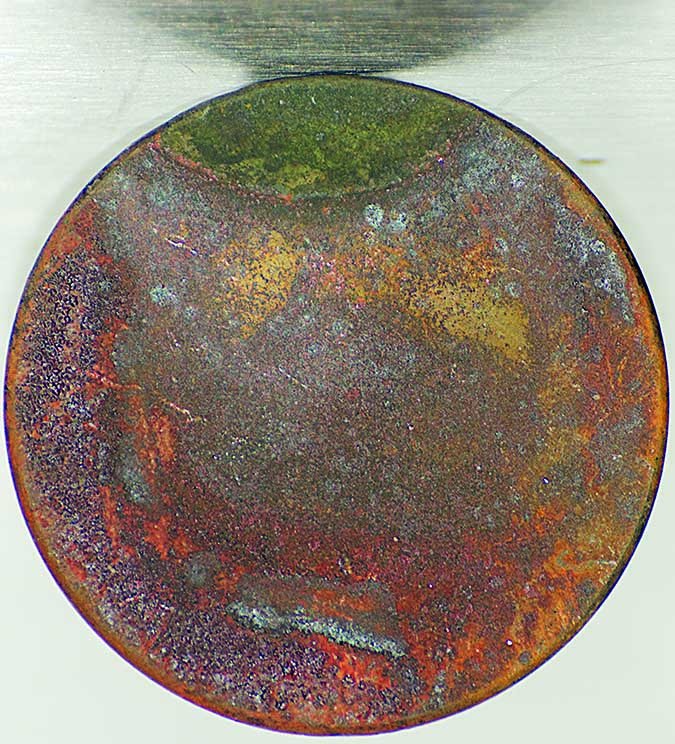
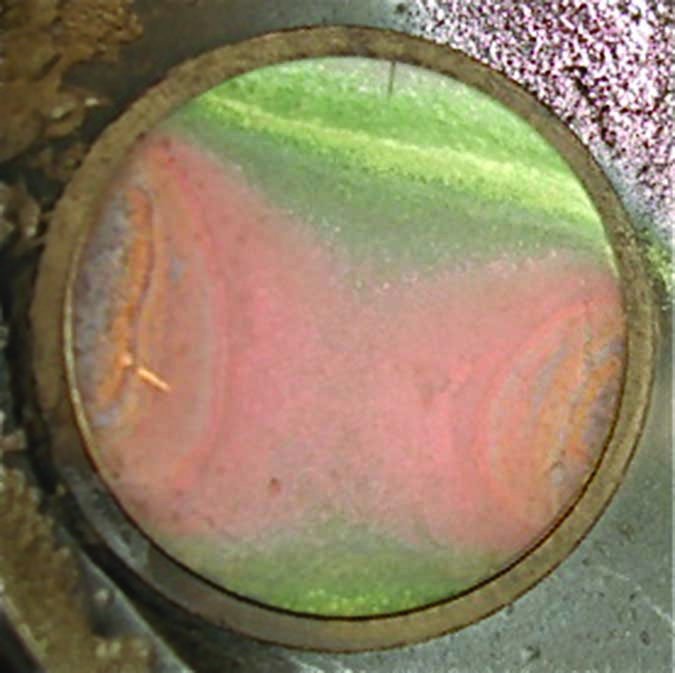
Cracking is perhaps the most pernicious type of cylinder failure. At right, the circle denotes a crack in the combustion chamber between a spark plug port and a valve. At a minimum, cracks result in low compression. At worst, they portend potentially catastrophic failure of the cylinder and/or engine, including the possibility of fire. Generally, any crack in a cylinder grounds the airplane until it’s replaced.
Valve Failures
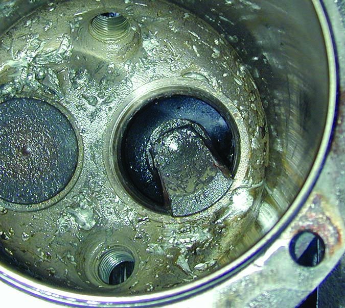
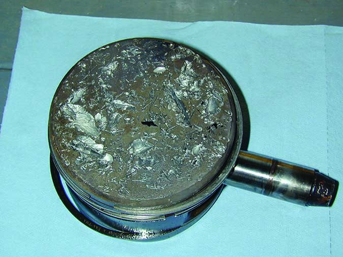
Cylinder valves—especially exhaust valves—operate in extreme conditions. When a portion of the valve system (the valve itself, the seat, the spring, lifters and, in some designs, a mechanism to rotate the valve) wears, compression can suffer, resulting in reduced power output. When valves break, as shown in the bottom two images at right, the pieces can bounce around in the cylinder and into the piston, making lots of bits of metal and ruining your whole day.
Head/Barrel Separation
The aluminum cylinder head and steel barrel are screwed together with precise fit and tolerances. Over the years, there have been problems related to barrel threads not engaging completely with the cylinder head, improperly applied torque and poor-quality casting of the aluminum material used to produce the head. It’s important to recognize that cylinder head/barrel separation carries great potential for complete engine failure and a forced landing.
Heat Is Enemy #1
The engine itself, of course, is cooled by air flowing through the cylinder fins, which offloads the heat energy resulting from the combustion within. While the rest of the engine, i.e., the crankcase and the components within it, also get hot, they never approach the temperatures cylinders experience. Too, the engine’s lubricating oil carries away internal heat, often to be tossed overboard via an oil cooler. But the cylinders are the hottest part of the engine, and in the interest of overall longevity, we need to keep them cool.
Don’t believe it? For a 2009 article in sister publication Aviation Consumer, PennYan Aero’s Alex Courtney told the magazine, “Heat is one of the top two things. Cylinder life is directly related to heat and oil cleanliness.” Since the underlying technology and metallurgy haven’t changed since then, neither has the recommendation. Keep the jugs cool using whatever means at your disposal—improving and repairing baffling, opening cowl flaps, increasing airspeed, running well rich of peak exhaust gas temperature (EGT) or lean-of-peak, or some combination that works for you and your engine—will help prevent both cylinder cracking and exhaust valve-guide wear. And change the oil often, of course.
One question pilots often have is, how hot is too hot? Unfortunately, many airframe manufacturers have, at least in the past, published cylinder head temperature (CHT) limits that many observers believe are too high to ensure longevity. Many of those observers either repair, overhaul or study aircraft piston engines. They generally recommend maximum CHT values of 380 degrees F, which is quite a difference from the 460 degrees F many manufacturers allow.
Adrian Eichhorn
Adrian Eichhorn
Adrian Eichhorn
On the other end of the spectrum, is there is such a thing as a cylinder being too cold? In typical operations, the answer is no. Cylinder temperatures of, say, 280 to 320 degrees F may raise eyebrows, but there’s no real problem. If a cylinder goes very cold, however, say 100-140 degrees, it likely isn’t experiencing regular, steady combustion—the engine and/or cylinder may have other issues. If they do, the pilot probably knows about it already.
Quality (Out Of?) Control
In the last few years, there have been several FAA airworthiness directives (ADs) against piston aircraft engine cylinders. The ADs generally call for increased inspection frequency, life limits or outright replacement of cylinders. They were developed after in-service cylinders developed certain specific failure modes, including cracks resulting from reduced wall thickness (AD 2009-19-07), and cracks near the exhaust valve and barrel separation (AD 2009-16-03). The ADs affected cylinders from Engine Components, Inc. (ECI), Superior Air Parts and Continental itself. Essentially, at one point or another, every cylinder was suspect except those manufactured/sold by Lycoming. Many—but not all—of those cylinders have been removed from service by now. But that hasn’t stopped the flow of ADs.
Recently the FAA added AD 2016-16-12, effective September 15, 2016, addressing cylinders manufactured by ECI for Continental IO-520/550 engines, and requiring that approximately 6000 cylinders (p/n AEC 631397) be removed from service. The AD is designed to prevent separation of the cylinder barrel from the cylinder head (see below).
When considering this and similar ADs, it’s important to understand engine and aftermarket parts manufacturers typically purchase raw stock or partially processed components from one or a few different suppliers. The materials used in the production of the raw stock can be the same for several purchasers, or may be specifically formulated according to instructions from the part manufacturer. Cylinder components arrive at the production facility and require machining, heat treating, testing/inspection and special assembly procedures typically using automated machinery. In other words, sufficient safeguards are designed into the manufacturing process that should minimize material defects. But that’s not always the way it works.
Nevertheless, operating an engine at high power settings, at high cylinder head temperatures or with leaking exhaust ports greatly increases the likelihood of cracks and other damage. It’s therefore important that careful, routine inspections are accomplished to detect cylinder cracks and other faults prior to partial or complete engine failure.
Cylinder Management Tools
There are four basic methods we can employ to manage and monitor condition of the cylinders on our piston engines. First and simplest—at least when considering the tools required—is a close, detailed visual inspection. When one is conducted, we’re looking for cracks, often highlighted by discoloration. Excellent lighting is mandatory, as may be an inspection mirror or magnifying glass. Many cracks may first appear to be a casting mark, so suspect features in the cylinder itself should not be dismissed as nothing to worry about.
A compression test is another way to check and verify a cylinder’s integrity. A typical test pumps pressurized shop air into the cylinder, usually at 80 psi, and measures the extent to which the air leaks out. Some leakage is normal, but if the cylinder is only able to hold, say, 20 psi, further investigation is mandatory. You may hear the air leaking past the valves. If it’s not, it’s either leaking past the piston rings and pressurizing the engine crankcase or it’s getting out through a crack.
A third way to monitor your cylinder’s health is engine oil analysis. When draining the crankcase during an oil change, some of the used oil is bottled and shipped off to a lab for analysis. The same basic testing is performed on powerplants like truck, boat and heavy equipment engines and is well understood. The lab analyzes the sample and send back a report on the materials it found in the oil, which can range from silica (sand and dirt) to iron (piston barrel) and other metals. Depending on the type of engine and the metal found, if any, a knowledgeable technician can narrow down a diagnosis to one or two specific components in the engine, not just the cylinders.
The Holy Grail of aircraft piston engine management, however, is the graphic engine monitor, a personal airplane avionics category that’s only about 20 years old. Through the magic of microprocessors, thermocouples and millivolts, a modern engine monitor can tell a pilot at a glance what’s going on in the engine, including but not limited to CHT, EGT and other parameters. It also can store this data, sampled at pilot-determined intervals, then make it available for analysis using a conventional spreadsheet, a custom application or an online service like Savvy Analysis.
Even so, the main thing an engine monitor tracks is heat. Which brings our discussion full circle: If you fly the airplane regularly, keep your cylinders relatively cool and crack-free, the chances of them making it to the engine’s next overhaul are quite good.


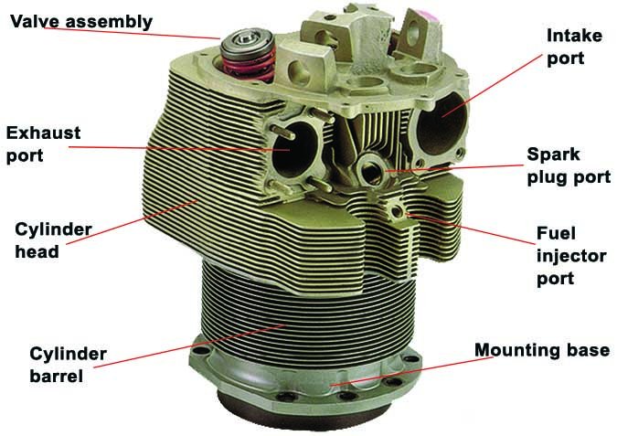
The last picture has an incorrect label. That is a thermocouple well, not a fuel injector port. The fuel injector port is located in the intake plenum.