
In 2015, a public-private partnership involving the FAA, pilot and industry organizations, plus airframe and powerplant manufacturers, and known as the General Aviation Joint Steering Committee (GAJSC), used accident data to identify in-flight loss of control as the leading cause of fatal general aviation accidents. A GAJSC working group determined we could substantially reduce the number of fatal accidents by equipping more light airplanes with angle of attack (AoA) indicators. Industry made this the number one target for improving general aviation safety and the FAA developed new certification policies allowing non-required safety enhancing equipment (NORSEE) were adopted that allowed installing safety improvement items such as AoA indicators with little more paperwork than a mechanic’s signature.
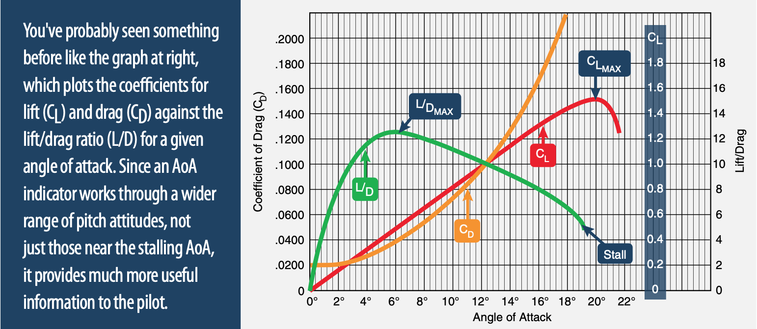
The new AoA indicators would not replace an existing certified stall warning system but would augment it instead. How is that supposed to enhance GA safety? Remember that the wing stalls at only one angle of attack but can stall at any airspeed. In fact, the typical stall warning system in small airplanes uses an angle of attack sensor as the primary data source, but it’s just off or on. Instead, an AoA indicator is more analog in nature, and provides valuable information in high-lift situations well before a stall warning system would activate. Put another way, the AoA indicator works throughout the range of pitch attitudes where a stall warning system only activates at the high extreme.
AIRSPEED VS. AOA
Until recently, the foremost proponents of using AoA indicators might have been naval aviators. Carrier-qualified pilots spend their time getting back aboard the boat in relatively slow, high-lift conditions well-suited for AoA instrumentation. That’s because airspeed-based sensors typically lose accuracy as airspeed decreases, thanks to the lower pressure they experience, but the AoA becomes more sensitive the slower you get. Put another way, at relatively low airspeeds, a slight change in speed often results in a proportionally greater change in AoA. The reverse also is true: at slow speeds, a large change in AoA may not be accompanied by a proportional change in airspeed.
Thanks to AoA sensitivity improving in high-lift conditions instead of deteriorating, it makes an ideal instrument to improve awareness of the stall margin. Having the indicator on the side of the glare shield makes it easy to glance at it while keeping your eyes on the runway environment. It’s hard to make a good landing if you haven’t been stabilized on the approach.
That’s one reason AoA is normally thought of as being useful only on the approach. What about a 60-degree banked turn where the stall speed has gone up by 41 percent? What about a skid on the base to final turn? These situations are other areas where an airspeed indicator alone shows its inadequacies, but where an AoA indicator shines. It’s also important to remember that, while an AoA indicator is a valuable safety device, it can also be used to establish the best rate or best angle of climb.
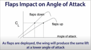
While helpful in improving awareness of stall margins, the low-cost light airplane AoA systems do not normally account for flap deployment. The critical/stall AoA is unaffected by weight and load factor but it does change with flap deployment. All of the low-cost systems make a compromise, such as choosing a sensor-mounting location that works over the full flap range, unless otherwise specified in their installation instructions.
MEASURING AOA
There are two basic ways that AoA can be determined. The first is through a sensor, hence the term “sensed AoA.” The second is to use inertial data to calculate the airplane’s AoA. This is called “derived AoA.”
There are also various ways to sense the angle of attack. Each measurement technique has advantages and disadvantages. One disadvantage of all sensed AoA systems is finding a suitable mounting location on the airplane. The location needs to be structurally sound but also have proper airflow to accurately sense the change in the relative wind. Airplane manufacturers use computational fluid dynamics programs to select the proper mounting location when an AoA indicator is required.
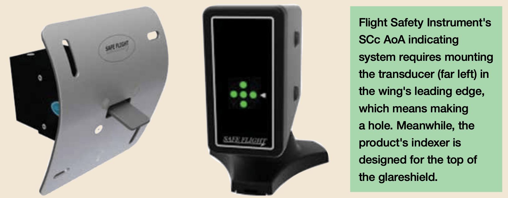
One technique is to measure AoA from a wing-mounted tab. The tab is connected to electronics to measure the force on the tab from the relative wind. They are mounted so that the stagnation point is behind the tab near the stall, pushing it forward. Safe Flight Instrument Corp. is the primary manufacturer of these lift transducer products. The disadvantage of this type of sensor is that you must cut a hole in the wing’s leading edge to mount the transducer.
Safe Flight’s SCc® is only approved for mounting on the right wing of an airplane with one of the company’s Lift Detector or Lift Transducer products mounted on the left wing. The reasoning is that the installation of the lift detector didn’t compromise the left wing’s structural integrity, and then mounting the SCc’s detector on the right wing in the same fashion won’t either. Hence, it is considered a minor modification. The disadvantage becomes an advantage in that both wings now are measuring the airflow/stagnation point change. Another advantage is the “tab” is less susceptible to sideslip affecting the measurement. (Disclosure: I retired from Safe Flight in 2017.) Safe Flight’s SCc’s components are pictured below.
Another popular method is differential pressure sensors which use two ports to sense the pressure difference. They are mounted such that as the AoA increases, the differential pressure between the two ports changes. Alpha Systems, Garmin and Levil Aviation are major suppliers of this type of AoA for light airplanes. The advantage is they are easier to mount. The disadvantage is they are more susceptible to a sideslip affecting the AoA measurement. To minimize such an outcome, many jets use differential pressure sensing.
A third offering is an airplane-mounted vane, such as is found on transport airplanes. For light airplanes, these are a wing or strut-mounted vane (small torpedo-shaped tube with a rear fin). This type of sensor is used by CYA, another AoA indicator supplier. The advantages are reduced susceptibility to sideslip and ease of mounting.
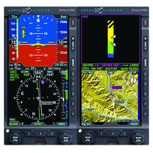
Lastly, there are derived/calculated AoA indicators based on inertial data. Aspen and uAvionix calculate AoA using inertial sensors. On the disadvantage side, the derived AoA is only as good as the sensor set. The higher the quality of the inertial sensors, the better the derived AoA. As the quality (and price) of the basic sensors drops, so does the accuracy.
Micro-electro-mechanical system (MEMS) gyros and accelerometers are proportional to the size of the microprocessor chip they’re mounted on. The larger the chip, the better the accuracy, but fewer chips are derived from a wafer, resulting in higher costs. Lower cost MEMS sensors often have issues with cross-axis interference and vibration. Lastly, transport-category airplanes have superb gyros and accelerometers to calculate the flight path angle (angle of the relative wind). Notably, Boeing and Airbus still rely on sensed AoA rather than derived AoA. That said, derived AoA has the huge advantage of often not requiring any additional hardware.
FLYING AOA
How do you fly AoA? It’s like flying airspeed, but is somewhat more sensitive to pitch while not sensitive to the airplane’s weight or load factor. For a typical VFR pattern, monitor AoA on the downwind-to-base turn and, most important, on base to final. If you get to the slow side, lower the nose and/or, if required, increase power.
On final, the airplane needs to have been slowed and trimmed for the approximate approach speed. Glancing at the AoA indicator will show if you are fast or slow. Gentle pitch inputs with small pitch-trim adjustments will keep you on-speed, and power will control the rate of descent. Flying AoA helps provide consistently stabilized approaches that leads to better landings.
Flying the best angle of climb (VX) on departure may require a little experimentation. On a calm day, do three takeoffs and hold your airplane’s best angle of climb airspeed. Don’t get so slow as to set off the stall warning or stall. If the engine coughs, it is imperative you get the nose down immediately. On each run, note the AoA indicator’s reading. The average of those three indications will serve as the target AoA for the next time you need to make a climb at the maximum angle. The AoA indicator also can help if you lose the engine on departure. But you need to get the nose down immediately. You cannot sit there watching increasing AoA and do nothing.
For larger airplanes where you need to calculate an approach speed (VREF) based on the airplane’s weight, an AoA indicator becomes a very handy cross-check. A normalized AoA of 0.6 will provide VREF (1.3 VS) airspeed. During autothrottle flight testing on a customer’s airplane, we had a consistently higher AoA on the approach than we were expecting. We were expecting 0.6, but if I remember correctly, it was around 0.7, with 1.0 being the critical/stall AoA. After double-checking the VREF calculations, we had the airplane weighed. It turned out it was heavier than the documentation stated. Crews were using an approach weight lighter than actual, resulting in a reduced stall margin as displayed on the AoA indicator. It’s not unusual that “stuff” doesn’t get added to the airplane’s logbook.
The FAA’s Pegasus initiative (Partnership to Enhance General Aviation Safety, Accessibility and Sustainability) has a YouTube video providing some basics on AoA basics and discussion of some of the products on the market. It also shows lift transducer and differential pressure systems in flight. The video offers a good, side-by-side comparison during common maneuvers: a normal approach to landing, stalls, steep turns and a slip. The video is available at: tinyurl.com/SAF-AOA.
The FAA’s research paper, DOT/FAA/TC-16/52, “Flight Test Results of Direct Measure and Derived Angle-of-Attack Systems for General Aviation Airplanes,” compares “sensed AoA” via Garmin’s differential pressure and Aspen’s “derived AoA.” The summary section of the report states: “Some effort was required to obtain satisfactory results from the sensed AoA commercial system, including relocation of the sensor. Following relocation, the sensed AoA system worked well, as did the derived AoA system using a commercially developed algorithm and Attitude and Heading Reference System unit.” A PDF of the paper is at: tinyurl.com/SAF-compare.
TRENDS
Initially after the GAJSC findings and implementation of NORSEE, there was a strong push to equip airplanes with AoA indicators. Cessna made Safe Flight’s SCc standard on the 172 in 2016. Lately, though, there’s been a decline in the number of retrofits: Bendix/King dropped its offering and sales of other systems have tapered off. What’s the reason for the decline? There seem to be two factors. One is the working group did a great job publicizing AoA’s safety advantages, but the educational push has declined as the aviation press lost interest. Second, and more significant, is the flight instructor community wasn’t 100-percent sold on AoA. Why? Most civilian flight instructors learned about AoA from classwork or textbooks, not out on the flight line. As one of those civilian flight instructors, when I was teaching, I rarely mentioned AoA. It was always airspeed control. Flight instructor refresher training could foster the use of AoA indicators, especially since, while the initial push to install AoA indicators has receded, the improved safety of angle of attack awareness has not diminished in the least.
Bob Teter is a retired CFI who also had a design/flight-test career with some of the biggest names in avionics.


