
by Greg Lewis
What characteristics make an aircraft a good platform to fly in instrument flight conditions? Much has been written on the subject, including a 1994 article by David Thurston in Aviation Safetys sister publication, IFR. In this first article of a series, well deal with the subject not trying to answer the question all at once but, instead, with detailed attention to certain specific characteristics. In each article, well describe ways for the non-test pilot to assess their aircrafts characteristics.
Of course, when driving through the clag and controlling the aircraft by reference to instruments, the number-one desirable characteristic is stability, both static and dynamic. This first article will focus on the relationship of stability to airspeed. Later articles will address other sides of the stability coin as well as discuss other important characteristics, such as wing loading and power effects. But before we go there, we need to clearly understand exactly what is meant by static and dynamic stability in general.
Stability
To visualize stability, consider a ball in a cup, such as the one shown in Example 1 in the diagram below. If the ball starts at the bottom of the cup and is then moved up one side and released, it will start moving downhill, back towards its starting point. Thats a definition of static stability: An object displaced from equilibrium tends to return towards equilibrium. The cup in Example 2, with its larger radius, is still stable, but the magnitude of its stability is less; the ball will start back toward its starting point less quickly. Example 3 is a ball on a flat table. If displaced, it wont start back at all but will stay in the displaced location.
Example 4 is an inverted cup. You could balance the ball on the top, but if it gets displaced and is released, the first motion would be away from its initial condition. This fourth example pretty well defines an unstable system. Another good illustration of instability is a broom, balanced in the palm of your hand with its bristles pointing up. If you dont act quickly to correct the brooms balance by moving your hand, it will quickly fall.
The same is true of an airplane trimmed for some airspeed in cruise or on approach. You would like the aircraft to be statically stable with respect to speed. If it is statically stable, its easier to fly. Small disturbances in airspeed will tend to correct themselves without pilot intervention. Thus, the pilot does not have to pay constant attention to controlling the aircrafts pitch.
Unstable systems can be flyable, however. In fact, the Wright brothers first Flyers were unstable in pitch but nonetheless flew. The problem is that unstable systems increase pilot workload. Imagine having to balance a broomstick in your hand while changing radio frequencies or reading an approach plate. It might be doable for a short time, but eventually the broom will hit the floor. If your broom is really an airplane, thats bad. And for that reason, all FAA-certified aircraft, when flown within their flight manual limits, are required to be statically stable with respect to speed changes.
Effects of Airspeed and CG
What makes an airplane stable in speed? Consider the two aircraft in the diagram to the right: The biggest contributors to pitch changes on the aircraft are the lift vectors created by the wing and the tail. Of course, the aircraft will pitch around its center of gravity (CG). In the top diagram, exaggerated for clarity, weve placed the CG forward of the wings lift, which normally acts at close to 25% of the wings chord aft of the leading edge. Therefore, the wings lift will try to pitch down the nose in this situation. The pilot adjusts the elevators position to generate a force on the horizontal tail designed to balance the pitching moment caused by the wings lift. So, with a forward CG, the tails lifting force is actually directed downward to help keep the nose in a level attitude.
What would happen if this aircrafts airspeed was disturbed? Suppose the aircraft became slower. This could be due to a gust, wind-shear, or even a distracted pilot inadvertently pulling up the nose. Of course, once the aircraft got slower, its angle of attack would increase. If the angle of attack became greater, lift produced by the wing would also increase. In this situation, the diagram makes it clear that the nose-down moment produced by the tail would also increase. Thus, if the aircraft slows for any reason, the change in wing-lift produced would drive down the nose, tending to increase the airplanes speed back towards its initial value.
What about the change in lift produced by the tail? At slower speeds, the tail would see an increase in angle of attack, similar to the wings increase. But here the tails lift is downward at trim so the tail starts off with a negative angle of attack. A small increase in the horizontal surfaces angle of attack would then result in a decreased downward force, reducing the nose-up moment produced by the tail. Thus, if the aircraft gets slow for any reason at all, the change in lift produced by the tail would tend to drop the nose downward, increasing the airplanes speed back towards its initial speed, which is also a stabilizing influence!
The result is that the change in lift produced by both the wing and the tail combine to drive the nose down if the aircraft is somehow disturbed to a slower speed than its initial trim condition. The aircraft must be statically stable if the CG is forward of the wing lift, unless of course there are significant pitch forces from something other than the lift produced by the wing and the tail, but that is not typically the case.
If the CG is moved aft of the wings center of lift, then at this trim condition the tails lift must increase to balance the nose-up moment generated by the wings lift. If again we somehow get slow and the angle of attack increases, the lift produced by both the wing and the tail will increase, so the nose-up moment from the wing becomes greater. At the same time, the nose-down moment generated by the tail also increases. The aircraft will pitch up or down depending on which of these two moments grows faster. The aircraft could be stable, neutral or unstable.
The result is determined by how far aft the CG is from the wings center of lift. Note that the aircraft is always stable with the CG forward of the wing lift. As the CG is moved aft, the aircraft becomes less stable. Once the CG is far enough aft of the wings center of lift, the aircraft becomes neutrally stable. Further aft and the aircraft becomes unstable with speed changes.
An aircraft unstable with speed changes would be harder to fly. Get just a little slow and, without pilot corrective action, the aircraft would tend to pitch up and get slower all by itself, and vice versa.
A Real-World Test
To see if your aircraft is statically stable with respect to speed, load the aircraft close to its aft CG limit (your worst case for speed stability), and trim it for cruise or approach speed. You want to be able to take your hands off the controls without any pitch changes. Then, leaving the power and trim alone, raise the nose to slow down a small amount. Then, release the controls from a steady speed below the initial speed and the nose should start to pitch down.
The opposite is also true-accelerate a small amount by holding the nose down, then release the controls from a speed above trim and the nose should start to pitch up. All certified aircraft, flown within the type certificates CG limits, should exhibit this kind of static stability.
How Much is Enough?
So, you may be asking yourself, whats the big deal? All certified aircraft are required to be speed-stable, so why would one aircraft be better than another? Well the answer is that different aircraft could exhibit different levels of stability. Too much stability could make the aircraft sluggish and unresponsive to pilot inputs. Too little stability could make the aircraft more difficult to control precisely without high levels of pilot workload.
If we graph the relationship of force to speed, we can calculate the rates of change between these two characteristics. The FAAs minimum value of force per speed for light aircraft isnt a specific number, but rather a qualitative requirement that the forces be stable and clearly perceptible to the pilot. By contrast, large transport aircraft are required to have a change in force of at least one pound for every six knots of airspeed. That would certainly meet the light aircraft requirement for clearly perceptible forces and isnt a bad minimum-force target for the pilot searching for an aircraft with good flying characteristics.
Control System Friction
But even more important than the numerical slope may be the interaction of the slope with friction in the control system. All mechanical flight control systems have friction. The impact of friction present in a control system will cause a non-linearity in the variation of force with speed: The force required to move a control the same amount will differ with the aircrafts speed.
Suppose an aircraft is trimmed for hands-off, level flight. If the pilot applies a very small force up or down, nothing will happen due to the friction in the control system. This can be understood by thinking about what happens if you push lightly on a chair (hopefully not one on glassy ice or well-oiled ball bearings!). For some small, measurable force, the chair wont budge. As you gradually increase the push-force on the chair, you will eventually overcome the frictional forces that prevented the chair from moving and then the chair will start to move. The exact same thing is true of the elevator of your aircraft.
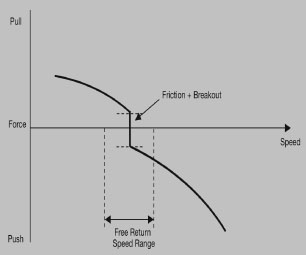
For some hopefully small force, the elevator, and thus the aircrafts speed, wont change as you begin to lightly pull from that initial, hands-off, trimmed condition. Until you exceed the friction band. After that, additional force moves the elevator to pitch up the nose and the airspeed will decrease. The same is true as you push. When the aircraft is trimmed, the total force that can be applied without moving the elevator is called the friction and breakout force in the control system, as shown above. The breakout part refers to the extra amount of force needed to take up all of the slack in the control system after youve made the yoke move but before the elevator actually moves. But in the cockpit you can only see the combined effect of the friction and breakout. The control system will pretty much have the same friction and breakout whether youre at trim speed or 40 knots slower or faster. And that fact means that if you slowly relax force from speeds above or below trim you will get to zero force at a speed above or below the original trimmed speed.
The range of speeds within which you can stabilize with a single trim setting is called the free return speed range (FRSR), which is shown in the diagram on page 14. The size of the FRSR is determined both by the magnitude of the friction and breakout forces, and by the slope of the force-vs.-speed curve. Large friction and breakout forces will foster large FRSRs. Likewise, shallow force gradients will cause larger FRSRs. Since aft CGs are less stable, the aft CG limit is the worst case for large FRSRs.
If we have a large FRSR, then the aircraft will be hard to trim precisely and it will tend to stay off the desired speed if disturbed an amount within the FRSR. This will increase pilot workload when trying to fly a precise speed in IMC.
The military puts an upper limit on the amount of friction in the control system (in pitch, a maximum of seven pounds). Civil certification rules set the limit on the size of the FRSR, generally +10% of the trim speed.
Another Real-World Test
If you want to test your aircraft to see how it compares to those criteria, first trim it at a cruise condition or for an approach configuration and speed. Then assess the friction and breakout force by gently pulling and estimating the force required to move the nose up. If its easy and can be done with one finger-probably less than two pounds-very acceptable. If it feels heavier than a gallon of milk, you may have excessive control-system friction.
Another assessment is to look at the effect of friction on the FRSR. Raise the nose to slow down 10% below your trimmed speed, leaving the power and trim unchanged. Once the speed is steady, release the force slowly. If the nose drops and the speed increases, that is good. If the nose stays displaced and the speed is steadily 10% slow, then again there may be too much friction in the system and/or the force gradients are too low. For completeness you should check the aircrafts nose-down reaction and speeds above trim speed as well. For good data, all of these evaluations require smooth air with absolutely no turbulence.
There are many things that make a good instrument-flying aircraft and in future articles well explore more of them, including lateral-directional static stability, dynamic stability and power effects.
Also With This Article
“Visualizing Stability”
“Static Stability and Control System Friction Test”
“Stability and Center of Gravity”
-Greg Lewis is deputy director and an instructor pilot at the National Test Pilot School, Mojave, Calif., <www.ntps.com>.


