
Ludwig Wittgenstein was among the most difficult and abstract of philosophers. But that’s not how he started out. Wittgenstein was an early pioneer in aeronautical engineering. He published a treatise on propellers in 1911, just eight years after the Wright Brothers first flew at Kitty Hawk.
He went to England to learn more about aerodynamics, but once he got there he must have decided that propellers were just too difficult and switched to working in philosophy. I’ve always found propellers difficult, too, but I’m going to try to get into their details again before I switch to philosophy.
THE BASICS
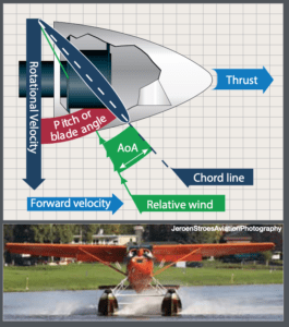
A propeller blade is an airfoil, and all of the airfoil concepts like chord line, relative wind and angle of attack apply. Angle of attack is the angle between the chord line and the relative wind. The force produced by a wing is called lift, and usually the force produced by a propeller blade is called thrust. Both depend on the same factors: air density, airfoil area, the true speed at which the device hits the air and angle of attack. Changing any of these changes the aerodynamic effect.
It turns out that angle of attack is one of the big tools for solving aerodynamic puzzles. You don’t need to know the angle with much precision, but knowing whether the angle of attack is high or low can help a lot. That applies to propeller blades as well as to wings.
But it’s not so simple. In analyzing a wing and its performance, there is only one wind direction to think about, the same relative wind that affects the whole aircraft. But a propeller has two relative winds: the aircraft’s relative wind and what you might call the rotational relative wind. What’s that? A propeller-driven airplane sitting on the ramp with the engine running has no relative wind, but the rotating prop is moving a lot of air. That’s the rotational relative wind. It moves from the prop hub perpendicular to the longitudinal axis. The prop, unless feathered, also pushes air aft. See the sidebar on the opposite page for a diagram of the how the FAA pictures the relationships.
When the airplane moves, the geometrical relationships between these winds become very complicated, because the aircraft relative wind is moving through the propeller area. And there are lots of other propeller-related complications. For the basics, let’s concentrate on single-engine airplanes with the propeller at the front. That’s already difficult enough to make a Viennese philosopher tear out his hair.
The propeller blade is an airfoil, so it’s worthwhile to look at how it moves air. That is, how much force can it generate?
Lift depends on several factors. One is the area of the airfoil, which the pilot can’t change. More area means more lift. Another is air density, which the pilot is aware of but is still unable to change in the case of a propeller. Denser air means more lift, which means that a prop or wing moving in a high-density altitude environment generates less lift.
Speed is another factor; more speed means more lift. The problem with propellers is that the parts further from the hub are going faster. When a big propeller turns at 2700 or more rpm, the tips are close to supersonic, if not already there, and generate a continuous set of sonic booms. That’s what makes, say, a Cessna 185 on floats so loud during takeoff.
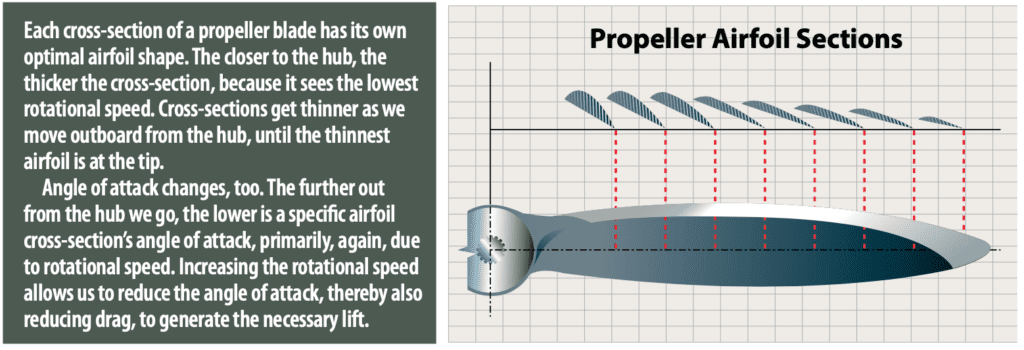
The biggest factor in propeller design is angle of attack. You have probably noticed that prop blades are twisted: the angle of attack is higher near the hub, where speed is low, and lower near the tip, where speed is high. The tradeoff between angle of attack and speed makes propeller design more complicated.
P-FACTOR
Right-turning tendency, or P-factor, is one of the most bizarre aspects of aircraft handling. Airplanes flying at low speed, or what’s effectively the same thing, at a high angle of attack, tend to turn to the left (or to the right in some airplanes whose propellers spin “anti-clockwise” as seen from their cockpits). The higher thrust from the downward-moving blade is the culprit. It’s on the right side, so it pushes the nose to the left. Even in low-powered airplanes, this effect is large, which is why flight instructors frequently, but I hope gently, remind pilots to use more right rudder, especially during climbs. Knowing how hard to push is part of getting to know an airplane. The desired effect is that the little cloud at 12 o’clock stays at 12 o’clock instead of sliding off toward early afternoon. Or, center the ball. Or hold the heading. If the airplane has rudder trim or a yaw damper this is a lot easier, but if it won’t push the rudder—you have to.
Aircraft angle of attack is higher during climb. Its effect on the downward-moving blade is stronger, so there’s more yaw.
Commercial pilots master this doing advanced maneuvers like chandelles. In a chandelle, the airplane is using climb power, but the airspeed is decreasing from the entry speed almost to the stall. As the airspeed decreases, the airplane angle of attack has to increase, and there’s more P-factor. The pilot has to push the rudder harder and harder throughout the maneuver. Even while turning left, you might still need right rudder to offset P-factor.
Propellers can be both simple, in the case of a fixed-pitch type, and rather more complicated, as with constant-speed or variable-pitch designs. They do share various characteristics, however, among which is the need to keep them and their spinners well-maintained and securely mounted.
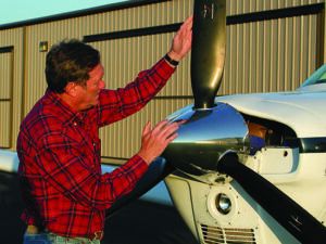
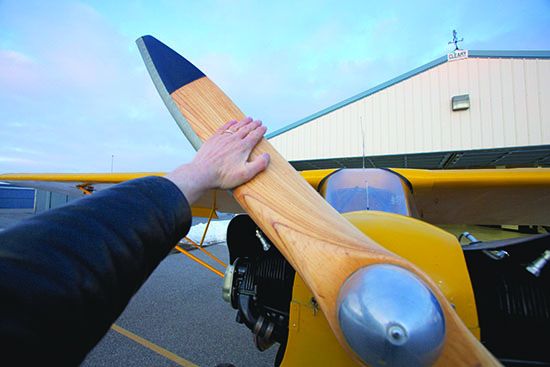
When inspecting a propeller before flight, it’s instructive to run a finger along the leading edge to identify nicks and gouges. Sharp-edged damage should be dressed by a professional to remove any stress risers, which could lead to cracking.
While you’re inspecting the blades of anything other than a fixed-pitch prop, try to twist them in their hub. They shouldn’t rotate. If they do, there’s a problem. Same with any oil weeping from the hub onto the blades, especially if it’s dyed red, which often is used to help pinpoint leaks. Finally, wiggle the propeller’s spinner, to verify it’s securely attached.
Metal propellers and their blades are subject to corrosion, just like any other major aircraft component. Between strippings and repaintings, it doesn’t hurt a thing to apply a thin film of lightweight oil to the blades to help keep corrosion at bay. — J.B.
SPIRALING SLIPSTREAM
Spiraling slipstream is another factor helping cause the left-turning tendency. Textbooks show air from the propeller spinning around the airplane in a helix or screw shape and hitting the left side of the vertical stabilizer. The most recent Pilot’s Handbook of Aeronautical Knowledge calls this a “corkscrew effect.” That’s probably a better description. It says, “The high-speed rotation of an aircraft propeller gives a corkscrew or spiraling rotation to the slipstream.”
I think this is incorrect. Why would the air twist around like that?
The answer is it doesn’t. Air that the propeller has moved is pushed out and back from the prop hub, period. The airplane flies through the rotating wind, and at certain speeds that air will come all the way around the airplane and hit the tail. The Handbook says that this is more likely at low speed. At higher speeds, the airplane is gone before the air has moved all the way around.
The difference between the aircraft sitting still, which only has rotational relative wind, and the moving aircraft, which has two kinds of relative wind, is huge.
CHANGING SPEED
Induced drag is one of the unfortunate by-products of lift. It slows things down. The effect is stronger when the aircraft’s angle of attack is high.
The propeller is an airfoil generating lift. Maneuvering and turbulence can increase its angle of attack, which increases its drag. It slows down.
A constant-speed propeller lets the prop speed back up by decreasing the blade’s angle of attack, allowing it, and the attached engine, to speed back up. Or in the opposite case when the prop slows, the mechanism decreases the angle of attack.
There are a lot of constant-speed designs, but the hydraulic types you’re most likely to fly generally depend on weights which centrifugal force pushes away as speed increases. Some kind of mechanical connection between the weights opens some kind of valve that changes some kind of pressure, usually oil pressure, that pushes the prop blades. The mechanism does not have to be in the propeller hub.
Going further, it is possible to feather a propeller, that is, rotate the blades so they are almost aligned with the aircraft’s relative wind. Since the thin part of the blade faces the relative wind, there is much less drag. The drag from a windmilling propeller is basically the drag of a solid disk of the same size, so the reduction is substantial.
The propeller’s angle of attack is very high when feathered, so the propeller stops.
Even if a propeller won’t feather, reducing the area facing forward has a big effect on aircraft drag. A typical constant-speed propeller only changes the blade angle a few degrees, but the drag reduction is still a lot. Next time you are doing simulated engine failures in an airplane with a constant-speed prop, bring the prop control all the way back into the low-rpm position. The temporary acceleration feels like you were driving a car with the parking brake on and then released it. This can improve glide performance a lot.
The 1946 Taylorcraft BC-12D I used to own had no electrical system and no starter. That reduced weight and so increased performance, but there was a catch: I had to hand-prop it to start the Continental engine. That’s called an “Armstrong starter,” even though, done properly, it does not take a lot of muscle.
I was instructed on hand-propping by an old, not bold instructor. How old? He told me that his instrument check ride included a four-course range approach. He showed me how to hand-prop the Taylorcraft safely, and supervised me on a bunch of starts. I went on to develop my own technique and never once came close to having a problem.
The BC-12D is not the easiest airplane to hand prop, and it is not the hardest. They’re all different. If you start flying an airplane with an Armstrong starter, you need to learn the procedure for that airplane. I tell my students to “fly the airplane you’re in,” but here it’s “start the airplane you are going to fly.”
GYROSCOPES
Gyroscopic effects have nothing to do with the geometry of the propeller. Replace the propeller with a 2-by-4 and the gyroscopic effect will be the same: the 2-by-4 goes clockwise, so the airplane attached to it has to go counter-clockwise. This is more of a roll effect but since in almost all airplanes roll and yaw are coupled, you’ll see some yaw, too.
ICE
Like wings, propellers are susceptible to icing. Icing can be mysterious, but it’s one of those mysteries that always ends badly. One general rule is that thinner airfoils accumulate more ice, so there might be more ice at the tips than at the hub, since the blade usually has a thicker chord than the tip.
Even a heated propeller can get ice accumulation. Usually the heaters operate on some kind of cycle like the left blade and then the right one. The momentarily unheated blade starts to pick up ice, which melts off when the heat on that side comes back on. It can sound like someone picked up a handful of gravel and threw it at the airplane.
THE END OF THE ATTACK
Angle of attack is the key to understanding what any airfoil is doing. And propellers are complicated because they have so many angles of attack.
But philosophers always try to find a simple underlying principle that will explain everything. Angle of attack isn’t simple enough for them, so here’s a simple formula for handling propeller complexity: Apply right rudder!
Jim Wolper is an airline transport pilot and mathematics professor. He’s also a CFI with single-engine, multi-engine, instrument and glider ratings.


Great article! Reminds me of my 1st Master’s Degree in Engineering Mechanics at UT Arlington back in 1971 (Jesus! That’s more than 50 years ago!) working with my thesis professor on the Stiffness and Mass Matrices of Twisted Beam Elements in Matrix Structural Analysis in their application to helicopter rotor blades and airplane propellers. Really fun stuff for some.
Looking so good , for your teachings about aviation safety, mine is only job there can I get