
Anyone who’s made it through primary training knows the importance of determining an airplane’s weight and balance. From that training, we know there are real limitations on how much it can carry and where that weight—whether in fuel, cargo or passengers—can be. We also know a lighter airplane performs better than a heavy one, and that weight concentrated near the fore or aft limits can affect aircraft performance.
In the August 2015 article “Some Weight In The Back,” this magazine explored what happens to performance when an airplane’s center of gravity (CG) is at, near or beyond its aft limit. But what about the opposite end of the CG range? What are the aerodynamic issues and consequences of inappropriately loading an airplane with a CG positioned near, at or beyond the forward limit? Just as when it’s aft, a forward CG presents important aerodynamic issues, which can adversely affect rate of climb, cruise airspeed, stall speed, fuel burn rate and airplane handling characteristics.
Aerodynamics 101
We all (should) know CG can be thought of as the airplane’s balance point for the nose down force and tail down force, and is the point along an airplane’s longitudinal axis (nose to tail) where its weight is concentrated. The three motions of an airplane—roll, pitch and yaw—all occur around the CG as a pivot point. The CG is represented by the red/white point in the two figures below.
Also of importance is the wing’s center of lift (CL), or center of pressure, which is represented by the bluw/white point in the diagrams. The arrows depict how CG and CL oppose each other, with the CL’s lift force vector shown in blue on the upper surface of the wing. Lift, the upward force on a wing acting perpendicular to the relative wind, is required to counteract an airplane’s weight which acts downward through the CG, represented by the red arrows. In stabilized level flight, the lift force is equivalent to the weight force: The airplane is in a condition of equilibrium and not gaining or losing altitude. Vectors of equal magnitude for lift force and weight force, are shown on Figures 1 and 2, depicting equilibrium.
Creative Commons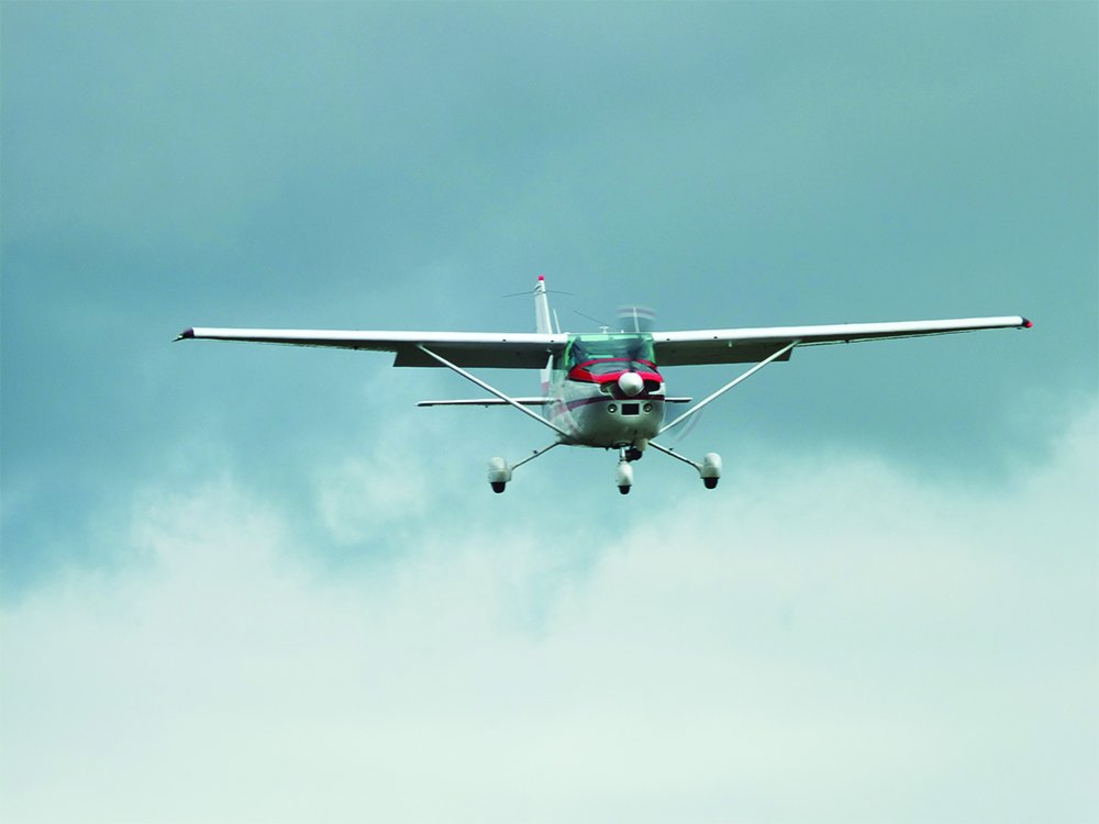
An airplane’s aerodynamic balance and controllability depends on the relative position of the CG and CL. It’s usually desirable for the CG to be positioned forward of the CL, which provides an appropriate restoring moment when the aerodynamic equilibrium is disturbed. At the same time, it should be understood that the CL moves fore and aft on a wing with changes in angle of attack (AoA).
Because CG is in a constant position as established by loading the airplane, as AoA increases, CL may move ahead of CG. (Generally, in the airplanes you and I fly, this is a bad thing.) If CL were to move forward of CG, it would generate a force to pitch the airplane’s nose further up to increase AoA more. As AoA decreases, the opposite occurs. It may be stated that an ordinary wing is somewhat unstable, and a horizontal tail is needed to exert an appropriate down force to make the airplane balance longitudinally.
Tail Loading
An airplane’s forward and aft CG limits may be represented by their position relative to and as a percentage of the wing chord (the imaginary line from the leading edge to trailing edge of airfoil, also known as the mean aerodynamic chord). Depending on airfoil and airplane types, the range limit can be approximately 10 to 40 percent or more of the chord.
Suppose an airplane is loaded such that the CG is at the aft range of the normal limit (Figure 1). Further presume the airplane weighs 2000 pounds and a tail-down force of 40 pounds is needed to balance the nose-down force. The horizontal stabilizer/elevator generates a “negative lift force”—or downward lift force exerted by the airplane’s tail—acting perpendicular to the relative wind that prevents the nose from pitching down. This is depicted in Figures 1 and 2 by the green arrows at the tail. The aerodynamic load of the tail-down force is as real as if a 40-pound weight were placed in the rear of the airplane. In fact, its 1G weight is no longer 2000 lbs as some may believe—the greater tail down force increases the airplane’s total weight force to 2040 pounds.
H. Raab
If the same airplane’s CG is positioned forward, either at or beyond the normal range, the airplane becomes more nose-heavy. To maintain straight-and-level flight under this condition, greater tail down force is required. This is accomplished by adding nose-up trim in most airplanes, which has the same effect as deflected the elevator nose-up to produce a greater tail-down force on the aft portion of the fuselage. The result is increased wing loading, determined by dividing the airplane’s total current weight by the wing surface area. This is depicted in Figures 1 and 2 by the different-sized green arrows at the tail.
Wing Loading
For purposes of discussion, let’s assume the new tail-down force represented in Figure 1 is 150 pounds instead of 40, a 275-percent increase. The math is presented in Table 1 on the preceding page. This greater tail-down force effectively increases the airplane’s total weight force to 2150 pounds which, in turn, increases wing loading. Implications of increased wing loading are higher liftoff/rotation (VR) and stall speeds (VS), longer takeoff and landing distances, a higher landing reference speed (VREF), and slower cruise airspeeds. Increased wing loading also increases power loading, the weight each unit of horsepower or thrust must carry around. As power loading increases, aircraft performance—rate of climb, cruise airspeed—decreases. Low power loading is a desirable characteristic associated with increased airplane performance.
As we also know, increasing AoA increases the lift force, up to a point. When the wing is at/beyond its critical AoA, the lift force decays rapidly and the wing stalls. Wing lift force is proportional to the square of airspeed, so that if we accelerated from 50 KIAS to 100 KIAS, a 100-percent increase, the lift force increases four-fold, presuming other factors in the equation remain constant.
To be consistent with the lift equation, if one factor on the right side of the equal sign increases, then another factor must decrease proportionately. In the case of increasing airspeed, AoA would need to be decreased. If AoA was held constant, the airplane would climb. Conversely, with a lower airspeed, a greater AoA is required for an appropriate amount of lift force to support the airplane’s weight. A practical example of the relationship of airspeed and AoA is when transitioning from normal cruise flight airspeed to slow flight airspeed. At the lower airspeed, AoA needs to increase appropriately to generate the necessary lift and, thus, maintain altitude.
Lift and Induced Drag
A consequence of greater lift force is increased induced drag, which varies directly with AoA and inversely with the square of airspeed. Induced drag occurs whenever a wing is generating lift. When producing a lift force, pressure on the upper surface of the wing is greater than on its lower surface. As a result, air flows from the region of higher pressure on the lower surface of the wing and below the wingtip, upward to the lower pressure area immediately above the wing. This causes a lateral flow of air outward from the lower surface of the wing and upward around the wingtip. One result is a rotational movement to flow at the wingtip that trails behind the wing. You know it as a wingtip vortex.
The heavier and slower the airplane, the greater will be the AoA required and the more intense will be its wingtip vortices. Thus, wingtip vortices are most intense during the takeoff, climb and landing phases of flight. Wingtip vortices exert a downward motion to the air, leaving the trailing edge of the wing. This downward push to the air—downwash—pushes down the airstream vector resulting, in tilting or bending the lift vector on top of wing rearward. The lift force is directed somewhat aft of perpendicular to the relative wind, resulting in a rearward lift force component. This is induced drag, a retarding force opposing the forward flight path.
Practical Implications
An airplane with forward loading requiring greater tail down force is aerodynamically heavier and, consequently, slower than the same airplane with a CG further aft. The salient point here is that pilots have a choice. By loading the airplane so its CG is positioned aft but within the approved CG and weight envelope, wing loading and induced drag are less, leading to increased airplane performance. The same airplane with a forward CG generates greater induced drag. In other words, if the CG is forward and normal cruise airspeed is desired, a higher power setting will be required to generate the additional thrust needed. That means greater fuel burn per hour, higher operating costs and decreased range.
As mentioned in our August article, pilots can easily determine the proper amount of weight that can be loaded aft to lessen an airplane’s tail-down force during their preflight planning when computing an aircraft’s weight and balance parameters. Pilots should carefully load the airplane by not exceeding the maximum allowable takeoff weight, positioning baggage and passengers properly, and ensure the fuel supply is adequate They also should determine the CG after the anticipated fuel burn. The CG may move to an unfavorable position and adversely affect the airplane’s flight and landing characteristics after consuming a large amount of fuel on a long cross-country flight.
Dr. Banner is a flight instructor at University Air Center, Gainesville Regional Airport (GNV), Gainesville FL, professor at the University of Florida in Gainesville, and instructor pilot in the U.S. Air Force Auxiliary / Civil Air Patrol. A CFII, MEI, he has 5000 hours flight time and owns a GCBC Citabria.


None of the diagrams are available at the time of writing this review.