
Wally, who was nearly thrice my age, was giving me a Taylorcraft checkout at a grass strip. I already had a tailwheel endorsement, but my insurer wanted time in-type for the new (to me) BC-12D. There were no systems to learn, so all I needed were a couple of stalls and about a hundred laps around the traffic pattern.
Wally and I got to talking about instrument flying. For his instrument rating check ride, he’d flown one approach in some fabric-covered taildragger using a four-course low-frequency range. That’s the old navaid that had four quadrants, broadcasting a Morse code “A” or “N” in each one. If you were on the boundary between the quadrants, the dots and the dashes canceled each other out. You were “on the beam” if you heard a steady tone. If you weren’t on the beam, knowing the Morse code for “A” and “N” would tell you which side of it you were on. The region right above the transmitter, which got no signal, was known as the “cone of silence.”
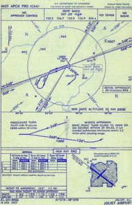
To fly an instrument approach using a four-course range, one flew a beam to the cone of silence, did a procedure turn if necessary, and descended to a minimum altitude while watching the clock. If enough time passed without seeing the airport, you would start the missed-approach procedure. The images below offer some examples of how it all worked. Remember, this was a non-radar environment, so there were no vectors to final.
The big thing Wally had to do was keep the airplane rightside-up while flying a heading, doing standard-rate turns, changing speed, climbing and descending, all while keeping an eye on a sweep second-hand. Because this navigation was done by ear, his eyes could focus on the instruments. Yes, it was simpler time, but perhaps a bit riskier. It was the Good Old Days.
THE CHALLENGE
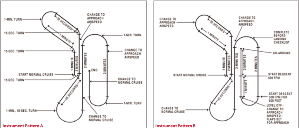
Wally probably practiced all of these skills using widely accepted instrument-flight training maneuvers known as Pattern A and Pattern B, which, until recently, were part of the FAA’s Instrument Flying Handbook. The patterns were a standardized way to develop all of the skills needed to fly instruments safely. Pattern A had straight-and-level legs at two different airspeeds connected by standard-rate turns, all of it based on timing. Pattern B had the same footprint but added a constant-rate climb and constant-rate descent. The images at the top of the opposite page give examples of both patterns, as well as their replacements in the current IFH.
Many people, myself included, worry that the almost universal presence of cockpit automation—e.g., sophisticated data bases, moving maps and coupled autopilots—have made pilots less competent when it comes to hand-flying the airplane. Pilots also don’t know how to leverage the avionics’ every feature. They tend to get really good at loading flight plans and approaches, but modern automation can do so much more. Maybe if we combined some of the old-school methods with the new technologies, we’d see improvements in competence and efficiency?
So here’s the challenge: Fly the old patterns with the automation. For example, tackle Pattern A with the autopilot engaged. This will use all of its horizontal modes. Once you’ve mastered that, Pattern B adds the vertical modes, if your automation has them. There are two ways to do this. Both involve picking a reference heading, which is easier if it’s a cardinal heading, i.e., north, east, south or west.
The first method is to use the heading bug and twist it to the new headings after the appropriate timing. For example, Pattern A starts with a one-minute leg. Set the heading bug to the reference heading and watch the clock for one minute. Then twist the heading bug 45 degrees to the left and start another one-minute leg. The next two legs are a turn and a shorter straight leg. Pretty simple, basic stuff, right? After another 45-degree turn, things get more complex, though, because there’s a speed change.
Speed changes are easy if your autopilot has altitude hold, but that doesn’t make them safe. Speed reduction is an energy reduction, so the technique is to reduce power (taking shock cooling into consideration), let the airspeed decay to the desired value, and then increase power to the approximate setting for the new speed, all while holding altitude. When hand-flying, it’s a good exercise in trim. When using the autopilot, you have all the normal flight-path management tasks, plus you have to monitor the magic to ensure it’s flying the pattern correctly. One risk is not increasing the power at the end. That can happen easily if ATC calls or you are checking the weather ahead or if a passenger wonders if you could turn up the cabin heat.
Once you’ve mastered the speed changes in Pattern A using the heading bug, you can try to fly pattern A using roll control instead. This varies from autopilot to autopilot, so here’s a chance to learn yours. Often the default is to have the autopilot in heading mode; I know one where that’s the only way to turn it on. You need to put the autopilot into “wing leveler” mode or something similar, if it’s available.
Now run through the exercise using the roll knob (or its equivalent) instead of the heading bug. This introduces a new problem for you to solve: the bank angle for a standard-rate turn varies with airspeed, so as you slow to approach airspeed, the bank angle has to decrease, and as you accelerate to cruise speed it has to increase. In Wally’s day, the turn needle was the primary instrument for bank during a standard rate turn, so he could use that to adjust the bank angle. It still is, and you may need to make that adjustment manually, depending on the autopilot.
WHERE AND HOW?
Looking at the two flight patterns on paper or a screen makes it difficult to imagine how much airspace they take up. You will fly at an indicated airspeed, which could be as low as 75 knots or as high as 150 knots or so. That doesn’t tell you how much real estate you’re going to cover, because unless you are at sea level, the true airspeed will be higher. And the wind will influence exactly which territory you’ll fly over, which is based on groundspeed.
The patterns have about four minutes of travel along the reference direction and about the same timing across, when you piece all the segments together. With a true airspeed of 75 knots in a no-wind condition, you cover 1.25 nm each minute, so the pattern takes place in a five-by-five nm box. At a true airspeed of 150 knots and no wind, you’ll cover 2.5 nm each minute, so now the pattern takes place in a 10-mile square.
Of course, finding a no-wind day at altitude is rare, so we have to take the winds into account. The patterns are supposed to take 15 minutes, which means a quarter of an hour of wind drift. A 20-knot wind would move the whole pattern five nm. The wind might blow parallel or perpendicular to the reference heading, which would lengthen one dimension of the 75-knot pattern to 10 nm, or it might be blowing diagonally to the reference.
There are a lot of places in the U.S. where it’s difficult to find a rectangle of those dimensions that avoids all Class B, C or D airspace, or special-use airspace, or known practice areas. You don’t want to be right on the edge of that airspace, either. Giving yourself a three-nm cushion makes for a 13-by-13 nm pattern (plus wind correction), which is even harder to find. If you run into this crunch, think about doing the pattern above or below the airspace, although even then it is wise to talk to ATC. If all else fails, a simulator—perhaps even something running on your personal computer—may be a fallback tool, depending on how its panel is configured.
It’s definitely a doable thing to program your avionics to fly these patterns, but there’s a lot of button-pushing and knob twisting in your future. The latest high-end electronic flight bags (EFBs) may make the task a bit easier, especially if they allow flight plans to be created offline and then uploaded to the panel-mounted avionics.
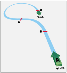
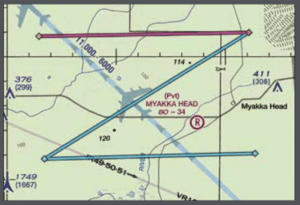
At right, for example, is a simple route created in ForeFlight and consisting entirely of user waypoints. Developing a flight plan consisting of the flight path in the original IFH patterns may be beyond your desire and/or the tools you have, but it can be done. Along the way, you might learn a few things about your avionics and how it all interfaces—or doesn’t—with your EFB.
MOVING UP
The next level of complexity would be to have the FMS or autopilot fly Pattern A or Pattern B from a programmed route. One way to do this is easy: fly a full approach, including a procedure turn and a missed approach. But you know how to do that. The challenge is to program your own patterns as a flight plan. It’s harder than it looks.
The leg lengths are now measured in distance rather than time, so pick a speed. That will be a groundspeed. Round numbers are multiples of 15, because they are easy to convert into miles per minute: 60 knots is one mile per minute, 75 is 1.25 miles per minute, 90 is 1.5 miles per minute and so on. At 120 knots, the one-minute legs chew up two miles. The additional challenge then is to adjust power to get the desired groundspeed. (This is not what ATC means when they give you a speed restriction, by the way. Those are all indicated airspeeds.)
The flight plan will start at a waypoint with a reference heading. It doesn’t matter which waypoint you pick, so for this purpose call it AVSAF with a reference heading of 090. Use a groundspeed of two nm/minute for practice, but for once it is appropriate to say, “Your mileage may vary.”
Now you really get to exercise your ability to enter flight plans. The next fix is 90 degrees from AVSAF at two nm. You need to follow your device’s protocol for defining a new waypoint at a bearing and distance from another. This can be tricky, but it has real-life applications, like when ATC gives you a crossing restriction of “Cross 20 miles north of AVSAF at niner-thousand.”
One common technique is to list the reference waypoint, bearing and distance, separated by slashes, so you would end up with something like AVSAF/090/2. Some navigators are fussy about format, so while you might be able to get away with something like AVSAF/90/2, you might need AVSAF/090/002. One flight-planning site uses no slashes, but every element has to be three digits, giving AVSAF090002. Using these systems, a common fix for turbine airplanes departing KSLC is TCH/005/055 or TCH005055.
Give the waypoint a name. Even in the age of Twitter’s 280-character limit, the convention is to allow five characters for fix names. One standard is to use the first letter of the reference fix, then the three-digit radial and then a letter to indicate (approximate) DME. In this case, the first waypoint would be A090B. There are problems if you want waypoints near and far from the fix: you might need “B” to indicate 20 miles (or 22, or 19), in which case you might use “A” for the two-mile fix.
Now that your fix has a name, you can define the next fix based on it, so the next fix in Pattern A could be A090B/045/002. Rinse, repeat
The one-minute turns present another problem. I have yet to run into a navigator that accepts user-programmed arcs. One option is to do a lot of geometry to define fixes along the arc, but a more useful method would be to program a hold with a direct entry at the fix. The device should do the initial turn after reaching the fix, and then the first outbound leg, etc. At that point you can exit the hold and go to the next fix. The larger turns in Pattern A could be done with a teardrop-entry hold.
It may not be possible to program the arc in some navigators, but then you can use the old “turn 10, twist 10” method to fly the arc.
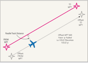
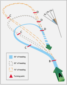
Modern navigators often have the ability to fly a parallel offset course, which can be useful sometimes. You select a leg of your flight plan and tell the navigator how far left or right of course you want to fly. The graphic above is adapted from the Garmin GTN 750 user manual.
I have used this to fly in more favorable conditions. You can also use it when your route gets close to special use airspace. If you think you’ll be too close, then offset a couple of miles away from the airspace to give yourself some cushion. (If you are IFR, you need a clearance to do this.)
If you and a friend are flying the same route in different airplanes, you can use the offset to prevent hitting each other. One flies the actual course, and the other offsets a mile. An offset to the right makes it easier to spot your friend to your left.
DEBRIEF
Even if you can’t do everything in the automated mode, you will learn a lot about how your navigator works, which can be just as important. But beware: none of this will help Wally fly the range approach in a Stinson Detroiter. That requires a different kind of smarts. In fact, it turns out the Good Old Days weren’t so good after all.
Jim Wolper is an airline transport pilot and retired mathematics professor. He’s also a CFI with single-engine, multi-engine, instrument and glider ratings.


