
As an avionics guy, I tempt owners to pull the big-dollar trigger on PFD upgrades. At the end of the day, I usually sleep well because most new owners who take my advice to the bank marvel at the cutting-edge touch of a PFD. The jump from round-gauge to glass flight instrumentation brings serious automation, huge amounts of data in one screen and offers a needed jump-start to old autopilots. But wrapping your head around the electrical interface and how the PFD interacts with other critical systems is a necessary challenge for safe operations. This is a challenge for the information-challenged, and some pilots I’ve turned loose after upgrading their panel do make me lose sleep.
288
It’s not getting easier. As if the wealth of data that comes standard on a PFD wasn’t enough, now there’s synthetic vision software that threatens information overload. Planning on going there? Don’t expect to fly your machine away from the avionics shop after such installation with sizeable amounts of proficiency unless you have a solid understanding of this new automation. This includes having a solid plan for the potential of component failure and laying the panel out in logical order.
Planning the New Layout
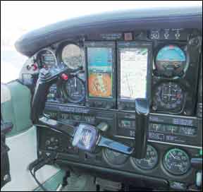
In Aviation Safety’s November 2011 issue, Tom Turner wrote about the challenges of flying the backup instruments in OEM glass cockpits. In these aircraft, you get what the manufacturer gives you and this isn’t always a convenient placement of backup primary instruments. The retrofit world—and PFD upgrades in particular—offers an advantage. Installing Aspen’s so called drop-in single-screen EFD1000 PFD in your panel includes at least some shuffling of instruments resulting in a custom layout that fits your scan.
The beauty of the cost-effective Aspen Evolution PFD is avoiding the big panel cut. Its chassis drops in the existing holes of the attitude gyro and directional gyro/HSI. Garmin’s larger retrofit G500/600 platform isn’t that easy but requires similar planning and relocation of the three primary backup gauges. This is the stage where you can make your transition to PFD flying easier or challenging. Here’s why.
Just like a true glass cockpit, retrofit PFDs require backup instruments to include airspeed, attitude and altimeter. Arguably, retrofit PFDs are an easier target for failure compared to all-glass aircraft as the sidebar on the opposite page explains. These backups need to be readily available someplace on the pilot’s instrument or sub-panel. Displacing them to the copilot’s side of the cockpit is outside of regulatory requirements.
As much as owners use PFD upgrades as an opportunity to build a redundant panel for the copilot, it’s out of the question, thanks to the FAA. Still, nearly any location on the pilot’s panel is usually fair game for backups. The takeaway here is that if the PFD were to fail, your eyes will be shifted to the backups. Plan for failure in the planning stages of the project.
I witnessed this calamity first hand on a flight test of a newly installed Aspen system. The owner, who was flying the aircraft from the left seat, thought he was being crafty when he initially designed a panel layout that had backup instruments in what most would argue to be inconvenient locations. Shortly after takeoff and while being vectored for a busy approach to put the new gear to the test, the Aspen failed (that’s why you perform shakedown flights before accepting the aircraft back). The owner—already out of his comfort zone with a new and foreign layout—couldn’t hold heading or altitude, or operate the autopilot, which worked a bit differently than before considering the Aspen’s GPSS integration. I don’t want to think what would happen if this happened in IMC.
Multiplex?
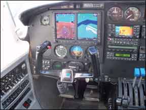
Planning your PFD upgrade also includes deciding how many screens you want. If you pick Garmin’s G500 or 600 systems, you’ll get a PFD/MFD combination housed in one bezel. I give the Garmin system the nod for an easier interpretation of the PFD. This really becomes obvious if you opt for the synthetic vision software. Garmin’s larger PFD area spreads the synthetic data out for a less-cramped display while Aspen’s screen is noticeably busier. But the trade-off for Aspen’s smaller screen is an easier installation that likely won’t require cutting the panel. That’s not going to be the case with a Garmin G500, which eats the entire six-pack on the pilot’s panel.
288
Learning the Interface
When owners venture on an avionics installation as major as a PFD retrofit, I’ll often recommend they study the new interface as if they were transitioning to a different aircraft. While this may seem like a draconian approach, consider that when you fetch the airplane from the avionics shop your airplane will in fact be different. I’ve witnessed the look of terror in an owner’s eyes when they slide into the pilot’s seat wondering how they’ll ever get the aircraft back home with this intimidating new gear and foreign switchology. Think of it this way: If you were transitioning to a more advanced aircraft and went to a professional training facility the likes of Flight Safety or Simcom, to name a couple, you would spend sizeable amounts of time learning the nuts, bolts and overall interface of the aircraft’s system.
No PFD system is self-contained, meaning there are critical supporting components mounted in and on the airframe to feed data to the screen. For example, Aspen’s EFD1000-series includes three major components: the display, an RSM (remote sensor module; a heading sensor with built-in GPS) and a temperature probe. In many applications, there’s an ACU (analogue converter unit) for converting analog signals to digital before passing them along to the display. The ACU also processes some of the autopilot’s signals. Garmin’s G500/600 has more independent remote components, including the GDU620 display, a GRS77 AHRS, GDC74A air data computer, a temperature probe and GMU44 magnetometer.
Despite the complexities and contrast between a steam-gauge panel and the new one, you don’t have to go to an expensive training facility to learn your system. A good avionics shop makes it a point to thoroughly explain the interface to a new owner before they send them off after installation. The post-install flight test is also a good if not busy time to gain some understanding of how the system is interfaced. Aspen’s Flight Manual Supplement offers good representation of where each critical component of the system is located on the airframe. There’s also interconnect schematics that you don’t have to be an electrical engineer to decipher, perhaps with a little help from the shop.
When faced with a failure, you should be armed with a solid understanding of what makes the system tick—or flat-line as the case may be—in a real-world failure. That’s how professional pilots train and, in the world of modern avionics, that’s how you should train for a new PFD install, too.
288
Autopilot Interaction
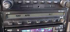
A huge hurdle for those new to retrofit PFDs is dealing with the autopilot interface. There used to be similar growing pains when owners installed traditional HSI systems that displayed both Nav and GPS course data. What information is being displayed on the needles? What data is the autopilot tracking? Since PFDs have integrated electronic HSIs, those hurdles don’t go away (although on-screen nomenclature tames that dragon to a certain extent). But in addition, PFDs bring several new tracking modes and conditions that if you aren’t in the game, can kill you.
For starters, the PFD can display on its EHSI any Nav and GPS system that’s connected. That’s new fewer than Nav1, Nav2, GPS1 and GPS2. On-screen data tags indicate what course data is being displayed. And whatever data is being displayed on the EHSI is feeding the coupled autopilot. Easy enough, right? Well, not exactly. GPSS steering changes all of that. One confusing scenario: You could program the autopilot to fly what’s programmed in the GPS by engaging the PFDs GPS steering but display raw nav data (say, a VOR frequency) on the EHSI. In that setup, what the EHSI course pointer is displaying isn’t what the autopilot is flying. Setting it up that way on purpose for crosscheck purposes is one thing. Mis-programming it is another matter and the unsuspecting pilot could find the autopilot taking him someplace he doesn’t want to go.
Lastly, the GPSS interface that comes with PFD upgrades might add capability to an old analog autopilot but they won’t fix broken ones. Worn servos, problematic computers and intermittent harness connections won’t go away but will make the transition more frustrating.
Putting It All Together
There’s no question PFD upgrades are major and time-consuming installations drastically changing the way you fly the aircraft. Despite all the things that can go wrong with such a retrofit, they offer more reliability and accuracy than the primary steam gauges they replace. Of course, performance is only as good as the quality of the installation.
Which PFD system is best for your flying and aircraft? To me, Aspen’s single-screen EFD1000Pro hands down makes the most sense for lesser aircraft with the ease of adding two additional screens and synthetic vision down the road. For higher-end applications where synthetic vision is a driving factor, get quotes on a multi-screen Aspen and a Garmin G500. Of course, Avidyne could give both manufacturers a headache when they release their PFD4000, which promises an easy electrical installation with a big-screen PFD at small-airplane prices.
Larry Anglisano is the Avionics Editor at sister publication Aviation Consumer. He also works with an avionics shop in Hartford, Conn.


