
Flying behind air-cooled powerplants, free of radiators or coolant tanks, it’s easy to forget most aircraft still need liquids of some type to operate safely and reliably. When those fluids are put under pressure to actuate a mechanism, we’ve created a hydraulic system, sometimes defined as something “using pressurized fluid to drive machinery or move mechanical components.” It also can be defined as transferring “energy by pressurizing fluid to force movement of a slave to produce the action sought.”
288
The hydraulic system most commonly found on personal airplanes is the braking system, which uses human muscle power to apply the pressure necessary to stop. Hydraulics often are used in other general aviation aircraft systems, too, to swing landing gear or move flaps. Larger, heavier aircraft also employ hydraulics to actuate primary controls and, in some cases, their trim surfaces.
System integrity is paramount in any hydraulics circuit: Since it depends on pressure to work correctly, the system must be leak-free for maximum efficiency. The alternative invites compromise and a resulting failure at the least-welcome moment—the moment you next need that system to work. With an eye firmly fixed on personal aircraft, let’s look at how hydraulic systems are used and maintained, and how their seeming complex engineering can be deceptive.
Hydraulics Of The First Kind
Press the control inputs of any brake master cylinder—the one mounted to the top of a rudder pedal—and it moves a measurable distance to displace an equal amount of fluid in the so-called slave part of the system. In a typical disc-brake brake system used on aircraft (as well as automobiles and motorcycles), this is a piston in the caliper. The small movement of those caliper pistons exerts tremendous squeezing pressure on the rotating disc.
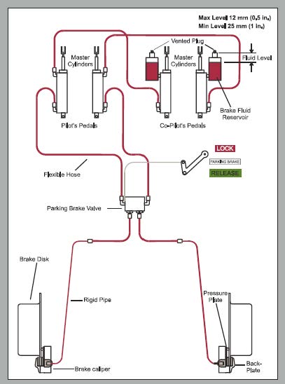
In turn, friction between disc and brake pad converts the aircraft’s kinetic energy into thermal energy and the discs heat up as the aircraft stops. In a typical piston-powered aircraft installation (see the system schematic at left), one or two reservoirs provide reserve fluid to independent master cylinders, one for each rudder pedal. Each master cylinder connects via hard tubing and/or flexible hose to the slave pistons in each brake caliper. Many hydraulic brake systems also include some type of mechanism to maintain pressure and applies the brakes for parking.
As simple as it is, the typical non-boosted, non-anti-lock braking system still possesses sufficient complexity to incorporate a variety of failure points. The primary things to watch for are leaks at the brake-fluid reservoir, the actuating master cylinders, the lines where they pass through structures or join other fittings and the brake calipers themselves. Both the master and slave cylinders (brake calipers), as well as the parking brake actuator, employ O-rings and other seals to prevent leakage. With age, however, these O-rings and seals can deteriorate and allow leaks. Other leaks can occur when corrosion attacks metal system lines or fittings and—like the internal rubber seals—flexible hoses can wear out from age or extreme environments. Sometimes, these failures can be sudden and with little warning, leaving the pilot with no braking power for that wheel.
Gearing Up
Beyond (relatively) simple braking systems, hydraulics also play a major role in many Part 23 general aviation aircraft, up to and including light jets and turboprops. Human muscles originally provided the force to manipulate an aircraft’s primary control surfaces, beginning with the original Wright Flyer. Today’s most modern GA designs continue that basic design, but as aircraft progressed from posting just-barely-aloft speeds to the realm of Mach numbers, their larger size, greater weight and higher control forces gradually made obsolete the Armstrong aircraft control method. The technology of hydraulics brought together the benefits of light weight and high power to magnify human input to manipulate aircraft systems controlling attitude, flaps and landing gear.
288
Motor- or hand-driven cranks driving chains or turning jackscrews moved the earliest retractable landing-gear systems, and those designs continued to be employed in military, commercial and private airplanes through the 1940s. Attitude control systems used yokes or sticks connected to control surfaces through cables, push rods or some combination. Foot pedals used cables to move the rudder; a separate handle positioned flaps.
At near the upper limit of aircraft with mechanical flight controls was the now-octogenarian Douglas DC-3. It used a 1930s-era conventional yoke and control column, plus rudder pedals, all acting through cables, pulleys and chains to move flight-control surfaces. Even the trim tabs for aileron, elevator and rudder are managed via cables connected to the cockpit. Meanwhile, the main landing gear of this big taildragger employed hydraulics.
The pressure-based system also was used for gear and flaps, in addition to its brakes.
Today, most cabin-class twins and turboprop designs—and virtually all business jets, from light on up—employ hydraulically driven landing gear systems. Cessna’s retractable singles, from the 172RG Cutlass, 177 Cardinal RG and up through the 210 Centurion use hydraulics in their landing-gear systems. The presence of adequate fluid is critical to these systems’ ability to lower and lock their gear. Conversely, Piper singles and some of its twins use a hydraulic system to raise the gear, which can free fall to down-and-locked.
Some aircraft use hydraulics to drive their flaps. These systems can vary widely and only focused study of a specific airframe can inform an owner or pilot on its intricacies, failure points, failure modes, maintenance and special procedures for handling failures. Some universals, however, still apply. For example, no hydraulic system functions optimally without the appropriate type and volume of fluid; attention to the capacity of reservoirs and accumulators—pressurized reservoirs—is critical to their performance.
Another must-know area is the special procedures for dealing with malfunctions. For some systems, the free fall covers extension of landing gear with failed hydraulics. This includes many Piper types. For others, including Cessna retractable singles, hydraulics are needed to position the gear in its down-and-locked state: no fluid or pressure, no gear. For most airframes, a reserve fluid source complements the main supply while a standby, manual pump is there to provide needed pressure when the engine- or electrically driven pump takes a vacation. Loss of all fluid will still cripple the system.
Still other aircraft need no stand-by pump. Bellanca’s Viking 17-30/31 series uses a powerpack mounted beneath the front seats with a self-contained fluid reservoir on top. A second, back-up reservoir is on the firewall. Losing all fluid from both reservoirs, though, leaves sufficient fluid in the powerpack’s pump and lines to lower the gear—once.
Flying right seat with a buddy in his Piper Arrow some years ago provided an opportunity for some useful debate and enlightenment—triggered, as it was, by a periodic, repeating load reflected on the aircraft’s amp meter. After cycling other equipment—and going off-frequency with ATC to shut down radios—we both heard what sounded like the landing-gear pump…running…briefly. The sound coincided with the ammeter spike, lasted about 15 to 20 seconds, then stopped. It then ran again 15 to 20 minutes later.
On the ground a couple of hours later, the Arrow’s owner discovered a hydraulic leak that let pressure bleed off its gear system. Upon sensing reduced pressure, the pump ran long enough to restore the system pressure. A further check of the airplane uncovered a low fluid reservoir for both the gear and brake systems. As the owner later noted, it pays to pay attention.
Primary Flight Controls
By the start of World War II, aircraft control systems increasingly employed hydraulic power to manipulate flight controls once moved solely by muscle power via cables or rods. With ever-bigger, more-complex aircraft came more and more hydraulics and greater redundancy in transport-category and military aircraft. Today, medium- and large-cabin business jets routinely employ hydraulics, when they’re not fly-by-wire designs.
In essence, a hydraulic system actuating an aircraft’s primary flight controls converts the pilot’s inputs at the yoke/stick and/or rudder pedals into pressure on the fluid it contains. The pressurized fluid then acts to move a servo proportional to the control input. Powerpacks provide the fluid pressure to move the slave servos; accumulators provide backup fluid and pressure for redundancy.
While pilots of transport-category aircraft may depend on maintenance crews to stay ahead of hydraulic-system problems, they still play a major role in detection. Flight crews know and understand their systems and become aware of known trouble spots through maintenance memos and training. Telltale signs can appear beneath anywhere hydraulic lines pass out of the airframe to the brake hardware, fittings to landing-gear actuators and at other places where signs of leaking lines, reservoirs or actuators would be apparent.
Beyond the accumulator in many aircraft, others employ ram-air turbines to drive standby pumps or electrical generators to run standby pumps. Like the accumulators, their functionality can be limited by their pressure-generation abilities and fluid-volume capacities. And while problems with hydraulic flight controls are rare, they often become legendary when they do occur.
Interestingly, many aircraft with hydraulic controls use them to boost a retained mechanical control system—one that provides backup in the event the hydraulics fail. A notable exception, of course, is the DC-10. On July 19, 1989, a McDonnell Douglas DC-10 operated as United Airlines Flight 232 departed the Denver (Colo.) Stapleton International Airport for Chicago. While in cruise at FL370, the fan disk of its tail-mounted #2 engine disintegrated. The uncontained failure allowed pieces of the failed disk to penetrate the airframe in several places, including all three hydraulic systems, draining hydraulic fluid from the perforated lines.
The flight crew, supplemented by a dead-heading captain and using only the remaining two throttles, gradually regained control and managed a crash landing in Sioux City, Iowa. While 111 died in the crash, there were 185 survivors, including the cockpit crew. As always, the pilots tended to Job 1: flying the airplane in circumstances never conceived by her designers.
A Little Pressure?
The main things you need to know about your aircraft hydraulic systems, if any, should be covered in the POH/AFM. If we were the pilots, we’d want to know how to pre-flight it, what kind of fluid it requires, how to replenish the fluid and what redundancy it affords. We’d also want to know what happens when electrical power fails, or when the powerplant turning the only engine-driven pump is secured.
Depending on the aircraft, we’d pay special attention during the pre-flight inspection for any telltale signs of leaks, like fluid on the ground near the brakes, under the belly or dripping from the wings. Such is never a good thing to find, but at least you now have a better idea of where it comes from and what systems might be affected.


